How to Use Ritto 7630: Examples, Pinouts, and Specs
Introduction
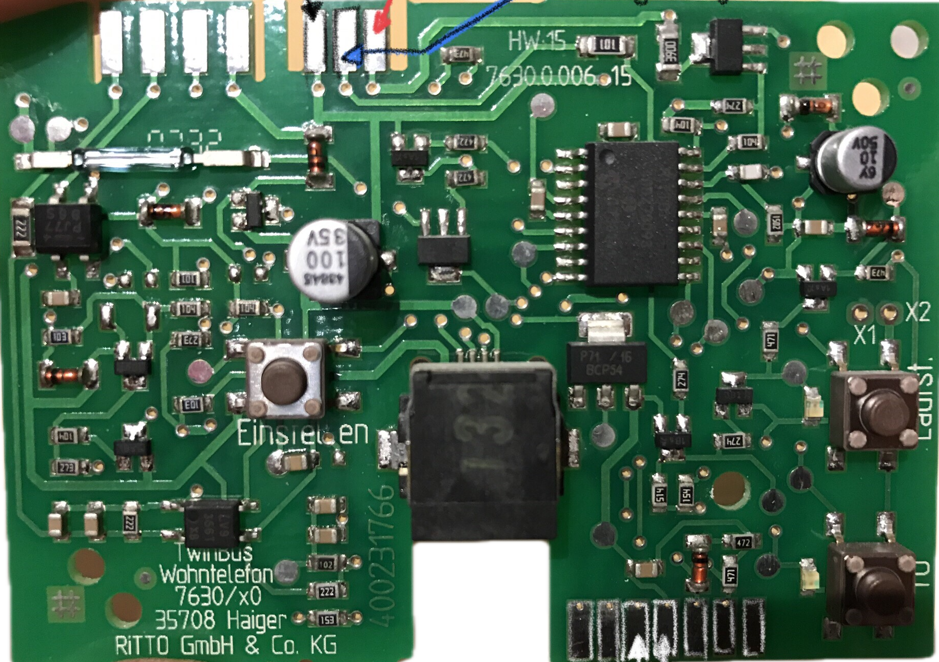
The Ritto 7630 is a door intercom system designed to facilitate seamless communication between the entrance of a building and its interior. Manufactured by Ritto, this device combines functionality with a sleek, modern design, making it an ideal choice for residential and commercial applications. Its user-friendly interface ensures ease of operation, while its robust construction guarantees reliability and durability.
Explore Projects Built with Ritto 7630

Explore Projects Built with Ritto 7630
Common Applications and Use Cases
- Residential buildings for secure visitor communication
- Office buildings to manage access control
- Multi-unit apartment complexes
- Commercial establishments for enhanced security
- Integration with smart home systems for advanced functionality
Technical Specifications
Key Technical Details
| Parameter | Specification |
|---|---|
| Manufacturer | Ritto |
| Part ID | 7630 |
| Power Supply | 12 V DC |
| Power Consumption | Max 1.5 W |
| Communication Type | Wired (2-wire bus system) |
| Operating Temperature | -10°C to +50°C |
| Dimensions | 90 mm x 150 mm x 30 mm |
| Mounting Type | Surface-mounted |
| Material | High-quality plastic housing |
| Audio Output | Full-duplex communication |
| Compatibility | Compatible with Ritto door stations |
Pin Configuration and Descriptions
The Ritto 7630 uses a 2-wire bus system for communication and power. Below is the pin configuration:
| Pin Number | Label | Description |
|---|---|---|
| 1 | BUS+ | Positive terminal for the 2-wire bus |
| 2 | BUS- | Negative terminal for the 2-wire bus |
Usage Instructions
How to Use the Ritto 7630 in a Circuit
- Power Connection: Connect the BUS+ and BUS- terminals to the corresponding terminals on the Ritto power supply unit. Ensure the polarity is correct to avoid damage.
- Door Station Connection: Connect the Ritto 7630 to a compatible Ritto door station using the 2-wire bus system.
- Mounting: Securely mount the Ritto 7630 on a flat surface near the desired indoor location.
- Testing: After installation, test the system by pressing the call button on the door station. Verify that the audio communication is clear and the device functions as expected.
Important Considerations and Best Practices
- Cable Selection: Use high-quality, shielded cables to minimize interference and ensure reliable communication.
- Power Supply: Only use the recommended Ritto power supply unit to avoid compatibility issues.
- Environmental Conditions: Install the device in a location protected from extreme temperatures and moisture.
- Maintenance: Periodically clean the device with a soft, dry cloth to maintain its appearance and functionality.
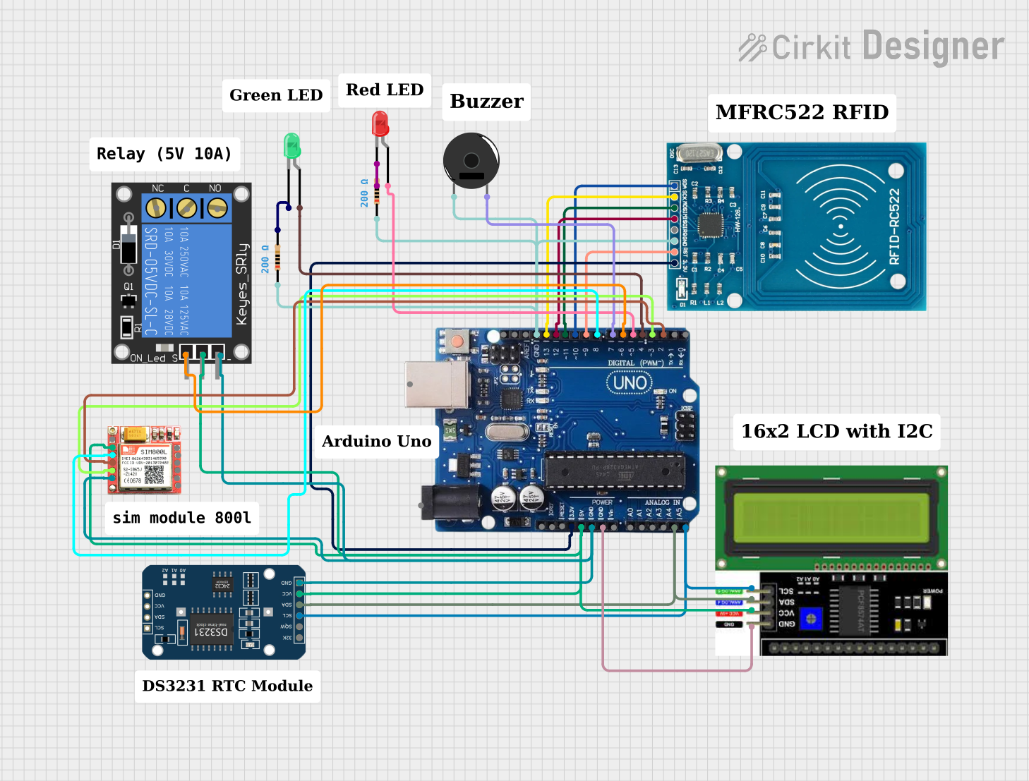
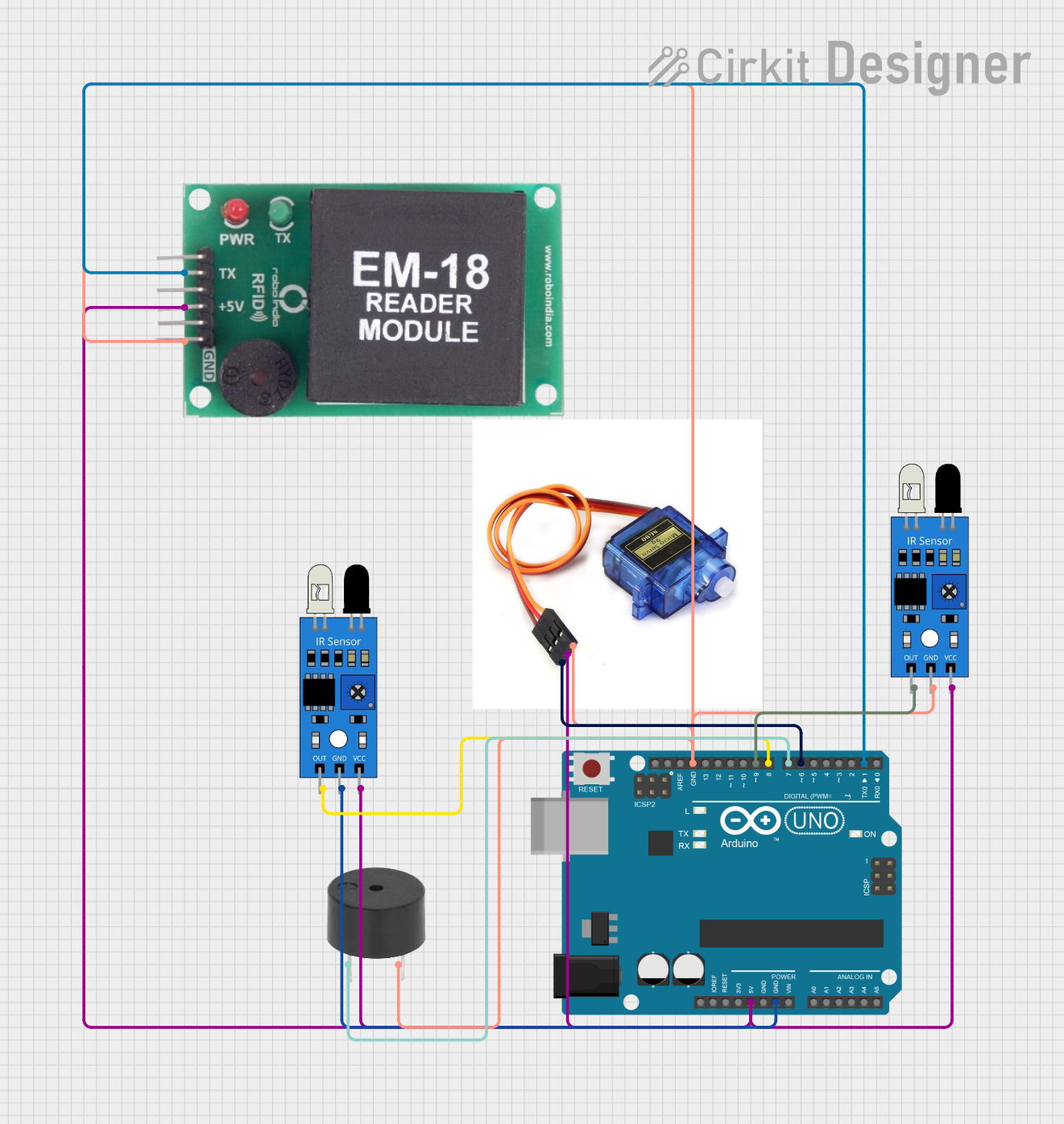
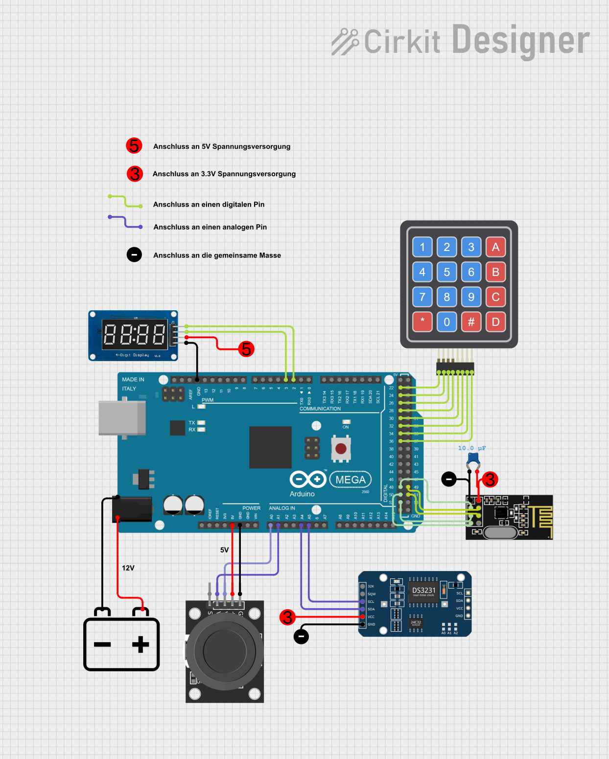
Arduino Integration
While the Ritto 7630 is not directly designed for Arduino integration, it is possible to interface it with an Arduino UNO for advanced automation. For example, you can use a relay module to trigger the door lock mechanism based on signals from the Arduino. Below is a sample code snippet for controlling a relay:
// Arduino code to control a relay for door lock mechanism
const int relayPin = 7; // Pin connected to the relay module

void setup() {
  pinMode(relayPin, OUTPUT); // Set relay pin as output
  digitalWrite(relayPin, LOW); // Ensure relay is off at startup
}

void loop() {
  // Example: Unlock door for 5 seconds when a condition is met
  if (/* condition to unlock door */) {
    digitalWrite(relayPin, HIGH); // Activate relay to unlock door
    delay(5000); // Keep door unlocked for 5 seconds
    digitalWrite(relayPin, LOW); // Deactivate relay to lock door
  }
}
Note: Replace
/* condition to unlock door */with your specific condition, such as a button press or a signal from a sensor.
Troubleshooting and FAQs
Common Issues and Solutions
| Issue | Possible Cause | Solution |
|---|---|---|
| No power to the device | Incorrect wiring or faulty power supply | Verify wiring and check the power supply |
| No audio communication | Loose connections or damaged cables | Inspect and secure all connections |
| Distorted audio | Interference or poor cable quality | Use shielded cables and check grounding |
| Device not responding to door station | Incompatible door station | Ensure compatibility with Ritto devices |
FAQs
Can the Ritto 7630 be used with third-party door stations?
No, the Ritto 7630 is designed to work exclusively with Ritto-compatible door stations.What is the maximum cable length for the 2-wire bus system?
The maximum cable length depends on the cable type and installation environment. Refer to the Ritto installation manual for detailed guidelines.Can the Ritto 7630 be integrated into a smart home system?
Yes, with additional hardware such as relays or smart controllers, the Ritto 7630 can be integrated into a smart home system for enhanced functionality.How do I reset the device?
To reset the Ritto 7630, disconnect it from the power supply for 10 seconds, then reconnect it.
By following this documentation, users can effectively install, operate, and troubleshoot the Ritto 7630 door intercom system.