How to Use TSL257: Examples, Pinouts, and Specs
Introduction
The TSL257-LF is a digital light sensor manufactured by ams OSRAM. It is designed to measure ambient light levels and provide a digital output via an I2C interface. This sensor is highly versatile and can be used in a variety of applications, including:
- Automatic lighting control systems
- Display brightness adjustment for screens
- Industrial and consumer light-sensitive applications
- Smart home devices and IoT systems
The TSL257 is compact, energy-efficient, and capable of accurately detecting light levels, making it an ideal choice for both professional and hobbyist projects.
Explore Projects Built with TSL257


Explore Projects Built with TSL257
Technical Specifications
Key Technical Details
| Parameter | Value |
|---|---|
| Manufacturer Part ID | TSL257-LF |
| Manufacturer | ams OSRAM |
| Supply Voltage (Vcc) | 2.7V to 5.5V |
| Output Type | Digital (I2C interface) |
| Spectral Response Range | 400 nm to 700 nm (visible light) |
| Operating Temperature | -40°C to +85°C |
| Power Consumption | Low power consumption |
| Package Type | 3-pin through-hole package |
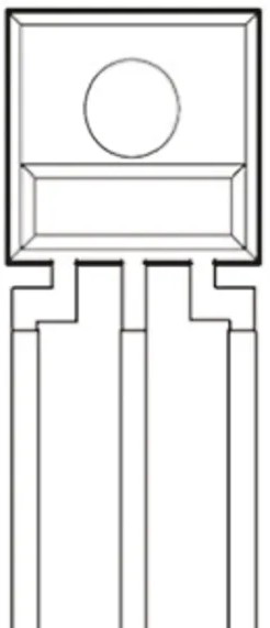
Pin Configuration and Descriptions
The TSL257-LF has a simple 3-pin configuration, as shown below:
| Pin Number | Pin Name | Description |
|---|---|---|
| 1 | VCC | Power supply pin (2.7V to 5.5V) |
| 2 | GND | Ground pin |
| 3 | OUT | Digital output pin (provides light intensity data) |
Usage Instructions
How to Use the TSL257 in a Circuit
- Power the Sensor: Connect the VCC pin to a 3.3V or 5V power supply and the GND pin to the ground of your circuit.
- Connect the Output: The OUT pin provides a digital signal proportional to the ambient light intensity. Connect this pin to a microcontroller's digital input pin or an ADC (Analog-to-Digital Converter) if needed.
- Read the Output: The sensor's output can be read directly as a digital signal. For more advanced applications, you can process the signal using a microcontroller.
Important Considerations and Best Practices
- Avoid Direct Sunlight: For accurate readings, avoid exposing the sensor to direct sunlight, as it may saturate the output.
- Use Decoupling Capacitors: Place a 0.1 µF decoupling capacitor between VCC and GND to reduce noise and ensure stable operation.
- Mounting: Ensure the sensor is mounted in a way that allows it to detect ambient light without obstruction.
- Interfacing with Arduino: The TSL257 can be easily interfaced with an Arduino UNO or similar microcontroller for light-sensing applications.
Example Arduino Code
Below is an example of how to use the TSL257 with an Arduino UNO to measure ambient light levels:
// Example code for interfacing the TSL257 with Arduino UNO
// This code reads the digital output from the TSL257 and prints the light level

const int sensorPin = 2; // Connect the OUT pin of TSL257 to digital pin 2

void setup() {
  pinMode(sensorPin, INPUT); // Set the sensor pin as input
  Serial.begin(9600);        // Initialize serial communication at 9600 baud
}

void loop() {
  int lightLevel = digitalRead(sensorPin); // Read the digital output from TSL257

  // Print the light level to the Serial Monitor
  if (lightLevel == HIGH) {
    Serial.println("Bright light detected");
  } else {
    Serial.println("Low light detected");
  }

  delay(500); // Wait for 500ms before the next reading
}
Troubleshooting and FAQs
Common Issues and Solutions
No Output Signal:
- Cause: The sensor may not be powered correctly.
- Solution: Verify that the VCC and GND pins are connected properly and that the supply voltage is within the specified range (2.7V to 5.5V).
Inconsistent Readings:
- Cause: Electrical noise or unstable power supply.
- Solution: Add a 0.1 µF decoupling capacitor between VCC and GND to stabilize the power supply.
Output Always HIGH or LOW:
- Cause: The sensor may be saturated due to excessive light or blocked by an obstruction.
- Solution: Ensure the sensor is not exposed to direct sunlight or completely covered.
Arduino Not Detecting Output:
- Cause: Incorrect pin configuration or wiring.
- Solution: Double-check the wiring and ensure the OUT pin is connected to the correct digital input pin on the Arduino.
FAQs
Q: Can the TSL257 detect infrared or ultraviolet light?
A: No, the TSL257 is designed to detect visible light in the 400 nm to 700 nm range.
Q: Is the TSL257 suitable for outdoor use?
A: While the TSL257 can be used outdoors, it should be protected from direct sunlight and environmental factors like rain or dust.
Q: Can I use the TSL257 with a 3.3V microcontroller?
A: Yes, the TSL257 operates within a supply voltage range of 2.7V to 5.5V, making it compatible with 3.3V systems.
Q: How do I improve the accuracy of the sensor?
A: Use proper shielding to reduce noise, avoid direct sunlight, and ensure the sensor is mounted in a stable position.
This documentation provides a comprehensive guide to using the TSL257-LF digital light sensor. By following the instructions and best practices outlined above, you can effectively integrate this sensor into your projects.