How to Use 0.96 OLED Screen: Examples, Pinouts, and Specs
Introduction
The 0.96 OLED Screen is a compact, low-power display module that utilizes organic light-emitting diodes (OLEDs) to produce bright and vibrant images. With a typical resolution of 128x64 pixels, this screen is ideal for displaying text, graphics, and simple animations. Its small size and energy efficiency make it a popular choice for embedded systems, microcontroller projects, and portable devices.
Explore Projects Built with 0.96 OLED Screen


Explore Projects Built with 0.96 OLED Screen
Common Applications
- Microcontroller-based projects (e.g., Arduino, Raspberry Pi)
- Wearable devices and portable electronics
- IoT dashboards and data visualization
- Compact user interfaces for appliances
- Educational and prototyping purposes
Technical Specifications
Below are the key technical details of the 0.96 OLED Screen:
| Parameter | Value |
|---|---|
| Display Type | OLED (Organic Light-Emitting Diode) |
| Resolution | 128x64 pixels |
| Interface | I2C (Inter-Integrated Circuit) or SPI (Serial Peripheral Interface) |
| Operating Voltage | 3.3V to 5V |
| Power Consumption | Low (varies with brightness) |
| Dimensions | 27mm x 27mm x 4mm (approx.) |
| Viewing Angle | >160° |
| Operating Temperature | -40°C to 85°C |
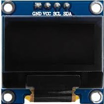
Pin Configuration (I2C Interface)
The 0.96 OLED Screen typically has 4 pins when using the I2C interface. Below is the pinout:
| Pin | Name | Description |
|---|---|---|
| 1 | GND | Ground (0V reference) |
| 2 | VCC | Power supply (3.3V or 5V) |
| 3 | SCL | Serial Clock Line (I2C clock signal) |
| 4 | SDA | Serial Data Line (I2C data signal) |
Pin Configuration (SPI Interface)
For SPI communication, the module may have additional pins. Below is a typical pinout:
| Pin | Name | Description |
|---|---|---|
| 1 | GND | Ground (0V reference) |
| 2 | VCC | Power supply (3.3V or 5V) |
| 3 | SCK | Serial Clock (SPI clock signal) |
| 4 | MOSI | Master Out Slave In (SPI data signal) |
| 5 | RES | Reset (active low) |
| 6 | DC | Data/Command control |
| 7 | CS | Chip Select (active low) |
Usage Instructions
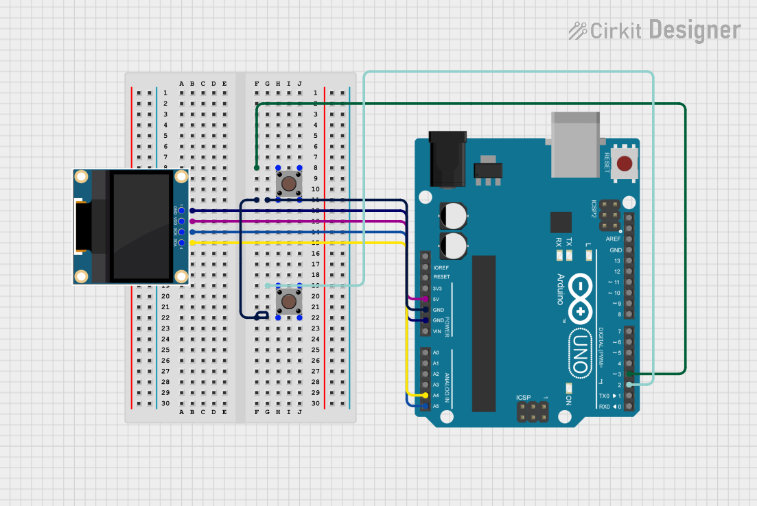
Connecting the OLED Screen to an Arduino UNO (I2C)
Wiring: Connect the OLED screen to the Arduino UNO as follows:
- GND → GND
- VCC → 5V
- SCL → A5 (I2C clock line on Arduino UNO)
- SDA → A4 (I2C data line on Arduino UNO)
Install Required Libraries:
- Open the Arduino IDE.
- Go to Sketch > Include Library > Manage Libraries.
- Search for and install the following libraries:
Adafruit GFX LibraryAdafruit SSD1306
Upload Example Code: Use the following example code to display "Hello, World!" on the OLED screen:
// Include necessary libraries
#include <Wire.h>
#include <Adafruit_GFX.h>
#include <Adafruit_SSD1306.h>

// Define OLED display width and height
#define SCREEN_WIDTH 128
#define SCREEN_HEIGHT 64

// Create an SSD1306 display object (I2C address 0x3C is common)
#define OLED_RESET -1  // Reset pin not used
Adafruit_SSD1306 display(SCREEN_WIDTH, SCREEN_HEIGHT, &Wire, OLED_RESET);

void setup() {
  // Initialize the display
  if (!display.begin(SSD1306_I2C_ADDRESS, 0x3C)) {
    Serial.println(F("SSD1306 allocation failed"));
    for (;;); // Halt execution if initialization fails
  }

  // Clear the display buffer
  display.clearDisplay();

  // Set text size and color
  display.setTextSize(1); // Text size multiplier
  display.setTextColor(SSD1306_WHITE);

  // Display "Hello, World!" on the screen
  display.setCursor(0, 0); // Set cursor position
  display.println(F("Hello, World!"));
  display.display(); // Render the text on the screen
}

void loop() {
  // Nothing to do here
}
Important Considerations
- Power Supply: Ensure the OLED screen is powered within its operating voltage range (3.3V to 5V). Exceeding this range may damage the module.
- I2C Address: The default I2C address for most 0.96 OLED screens is
0x3C. If the screen does not respond, check the address using an I2C scanner sketch. - Contrast and Brightness: Prolonged use at maximum brightness may reduce the lifespan of the OLED screen. Adjust brightness settings as needed.
Troubleshooting and FAQs
Common Issues
Screen Not Displaying Anything:
- Solution: Verify the wiring connections. Ensure GND, VCC, SCL, and SDA are correctly connected.
- Tip: Use a multimeter to check for continuity in the connections.
OLED Screen Flickering:
- Solution: Check the power supply. Ensure the module is receiving a stable voltage (3.3V or 5V).
- Tip: Use decoupling capacitors near the power pins to reduce noise.
I2C Address Not Detected:
- Solution: Run an I2C scanner sketch to confirm the address. Some modules may use
0x3Dinstead of0x3C. - Tip: Check the module's datasheet or documentation for the correct address.
- Solution: Run an I2C scanner sketch to confirm the address. Some modules may use
Text or Graphics Not Displaying Properly:
- Solution: Ensure the correct libraries (
Adafruit GFXandAdafruit SSD1306) are installed and up to date. - Tip: Verify that the display dimensions (128x64) are correctly defined in the code.
- Solution: Ensure the correct libraries (
FAQs
Q: Can I use the OLED screen with a 3.3V microcontroller?
A: Yes, the OLED screen is compatible with both 3.3V and 5V logic levels. Ensure the power supply matches the microcontroller's voltage.
Q: How do I switch between I2C and SPI modes?
A: Some OLED modules have solder jumpers on the back to select the communication mode. Refer to the module's datasheet for instructions.
Q: Can I display images on the OLED screen?
A: Yes, you can display images by converting them into a bitmap format. Tools like the LCD Assistant software can help with this process.
Q: What is the lifespan of the OLED screen?
A: The typical lifespan of an OLED screen is around 10,000 to 50,000 hours, depending on usage and brightness settings.