
How to Use ESP-12F: Examples, Pinouts, and Specs
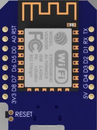
 Design with ESP-12F in Cirkit Designer
Introduction
The ESP-12F is a Wi-Fi module based on the ESP8266 chip, featuring a built-in TCP/IP stack and microcontroller capabilities. It is widely used for Internet of Things (IoT) applications due to its low cost, compact size, and ability to connect to Wi-Fi networks. The module is highly versatile and can be programmed using various platforms, including Arduino IDE, NodeMCU, and MicroPython.
Explore Projects Built with ESP-12F
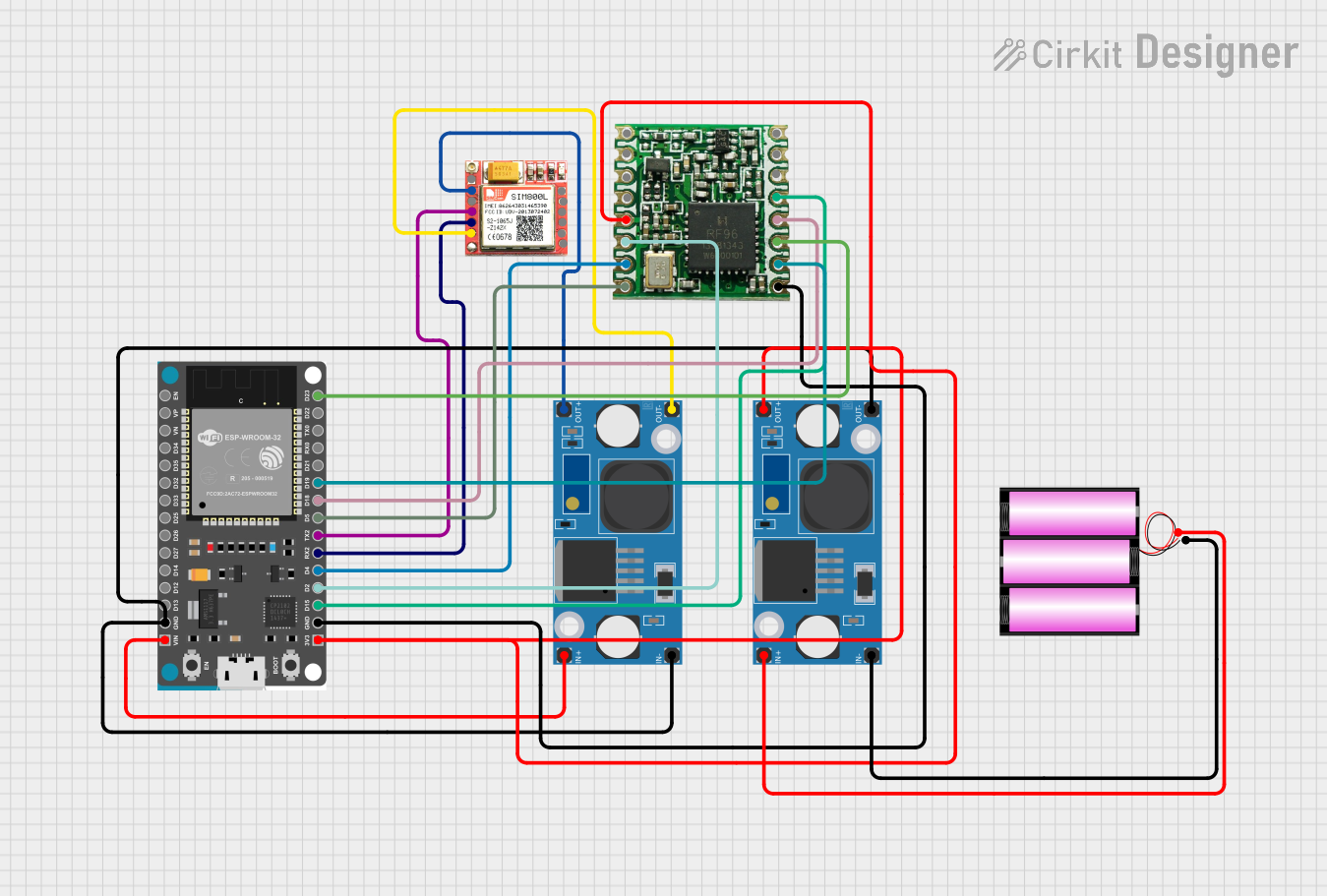 Open Project in Cirkit Designer
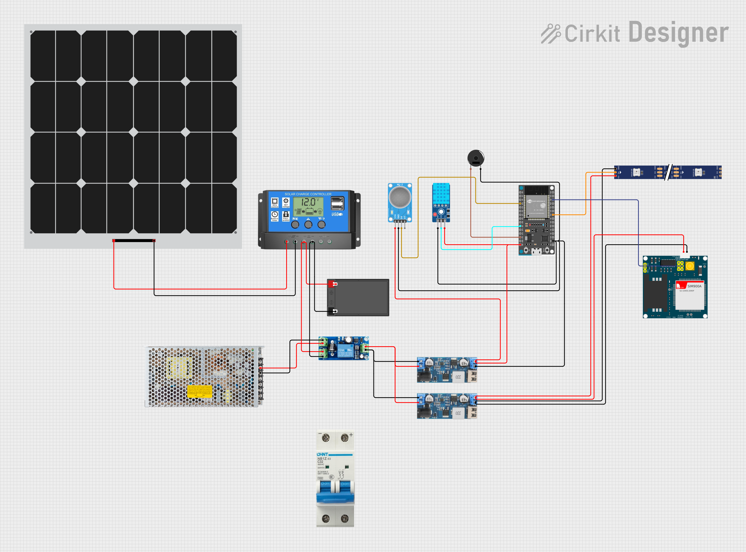 Open Project in Cirkit Designer
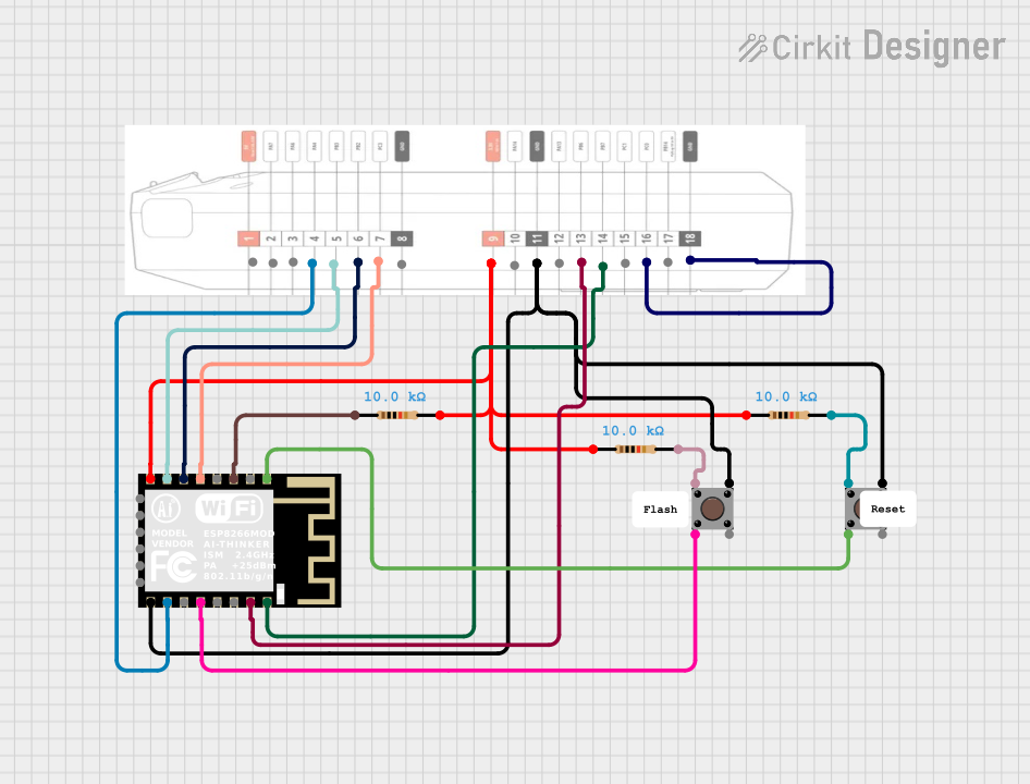 Open Project in Cirkit Designer
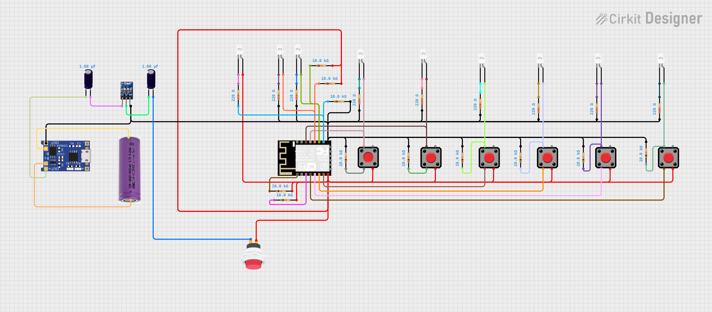 Open Project in Cirkit Designer
Explore Projects Built with ESP-12F
Open Project in Cirkit DesignerOpen Project in Cirkit DesignerOpen Project in Cirkit DesignerOpen Project in Cirkit DesignerCommon Applications and Use Cases
- Home automation systems
- Wireless sensor networks
- Smart appliances
- IoT prototyping and development
- Remote monitoring and control systems
Technical Specifications
The ESP-12F module is designed for low-power, high-performance wireless communication. Below are its key technical details:
Key Specifications
| Parameter | Value |
|---|---|
| Chipset | ESP8266 |
| Wi-Fi Standard | 802.11 b/g/n |
| Operating Voltage | 3.0V - 3.6V |
| Flash Memory | 4 MB (32 Mbit) |
| GPIO Pins | 11 |
| Maximum Current | ~170 mA (during transmission) |
| Deep Sleep Current | ~20 µA |
| Operating Temperature | -40°C to 125°C |
| Dimensions | 16 mm x 24 mm |
Pin Configuration and Descriptions
The ESP-12F module has 16 pins. Below is the pinout and description:
| Pin Number | Pin Name | Description |
|---|---|---|
| 1 | GND | Ground (0V reference) |
| 2 | GPIO16 | General-purpose I/O pin; can also be used for deep sleep wake-up |
| 3 | GPIO14 | General-purpose I/O pin; supports SPI clock (SCLK) |
| 4 | GPIO12 | General-purpose I/O pin; supports SPI MISO |
| 5 | GPIO13 | General-purpose I/O pin; supports SPI MOSI |
| 6 | GPIO15 | General-purpose I/O pin; must be pulled LOW during boot |
| 7 | GPIO2 | General-purpose I/O pin; must be pulled HIGH during boot |
| 8 | GPIO0 | General-purpose I/O pin; used for boot mode selection |
| 9 | GPIO4 | General-purpose I/O pin |
| 10 | GPIO5 | General-purpose I/O pin |
| 11 | RXD | UART Receive (RX) |
| 12 | TXD | UART Transmit (TX) |
| 13 | CH_PD/EN | Chip enable; must be pulled HIGH for normal operation |
| 14 | VCC | Power supply input (3.3V) |
| 15 | RST | Reset pin; active LOW |
| 16 | ADC/A0 | Analog-to-digital converter input (0V to 1V range) |
Usage Instructions
The ESP-12F module can be used in a variety of circuits and projects. Below are the steps to get started:
Basic Circuit Connection
- Power Supply: Connect the
VCCpin to a 3.3V power source and theGNDpin to ground. Ensure the power supply can provide at least 300 mA. - Enable Pin: Pull the
CH_PD/ENpin HIGH (connect to 3.3V) to enable the module. - Boot Mode:
- For normal operation, pull
GPIO0HIGH andGPIO15LOW. - For programming mode, pull
GPIO0LOW andGPIO15LOW.
- For normal operation, pull
- UART Communication: Connect the
RXDandTXDpins to a USB-to-serial adapter or microcontroller for communication.
Programming with Arduino IDE
The ESP-12F can be programmed using the Arduino IDE. Follow these steps:
- Install the ESP8266 board package in the Arduino IDE:
- Go to File > Preferences and add the following URL to the "Additional Board Manager URLs" field:
http://arduino.esp8266.com/stable/package_esp8266com_index.json - Open Tools > Board > Boards Manager, search for "ESP8266," and install the package.
- Go to File > Preferences and add the following URL to the "Additional Board Manager URLs" field:
- Select the correct board and port:
- Go to Tools > Board and select "Generic ESP8266 Module."
- Set the correct COM port under Tools > Port.
- Write and upload your code. Below is an example code to connect the ESP-12F to a Wi-Fi network and print the IP address:
#include <ESP8266WiFi.h> // Include the ESP8266 Wi-Fi library

const char* ssid = "Your_SSID";       // Replace with your Wi-Fi SSID
const char* password = "Your_Password"; // Replace with your Wi-Fi password

void setup() {
  Serial.begin(115200); // Start serial communication at 115200 baud
  WiFi.begin(ssid, password); // Connect to the Wi-Fi network

  Serial.print("Connecting to Wi-Fi");
  while (WiFi.status() != WL_CONNECTED) {
    delay(500); // Wait for connection
    Serial.print(".");
  }
  Serial.println("\nConnected to Wi-Fi!");
  Serial.print("IP Address: ");
  Serial.println(WiFi.localIP()); // Print the module's IP address
}

void loop() {
  // Add your main code here
}
Important Considerations and Best Practices
- Voltage Levels: The ESP-12F operates at 3.3V. Do not connect it directly to 5V logic or power.
- Power Supply: Use a stable power supply capable of providing at least 300 mA to avoid unexpected resets.
- Pull-up/Pull-down Resistors: Use appropriate pull-up or pull-down resistors on
GPIO0,GPIO2, andGPIO15to ensure proper boot modes. - Antenna Placement: Ensure the onboard antenna is not obstructed by metal objects to maintain good Wi-Fi signal strength.
Troubleshooting and FAQs
Common Issues
Module Not Responding
- Cause: Incorrect power supply or wiring.
- Solution: Verify that
VCCis 3.3V andCH_PD/ENis pulled HIGH.
Wi-Fi Connection Fails
- Cause: Incorrect SSID or password.
- Solution: Double-check the Wi-Fi credentials in your code.
Frequent Resets
- Cause: Insufficient power supply.
- Solution: Use a power source capable of providing at least 300 mA.
Garbage Data in Serial Monitor
- Cause: Incorrect baud rate.
- Solution: Set the serial monitor to 115200 baud.
FAQs
Can the ESP-12F be powered with 5V?
No, the ESP-12F operates at 3.3V. Use a voltage regulator if your power source is 5V.How do I update the firmware?
Use the ESP8266 Flasher tool and connect the module in programming mode (GPIO0LOW).What is the maximum range of the ESP-12F?
The range depends on the environment but is typically up to 100 meters in open space.Can I use the ESP-12F as a standalone microcontroller?
Yes, the ESP-12F has a built-in microcontroller and can run code without an external MCU.
By following this documentation, you can effectively integrate the ESP-12F module into your projects and troubleshoot common issues.