How to Use Actuator Motor: Examples, Pinouts, and Specs
Introduction
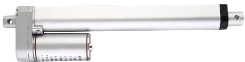
An actuator motor is a device that converts electrical energy into mechanical motion. It is commonly used to control the movement of mechanisms or systems in automation, robotics, and industrial applications. Actuator motors are integral to systems requiring precise motion control, such as robotic arms, conveyor belts, and automated valves. They are available in various types, including DC motors, stepper motors, and servo motors, each suited for specific tasks.
Explore Projects Built with Actuator Motor
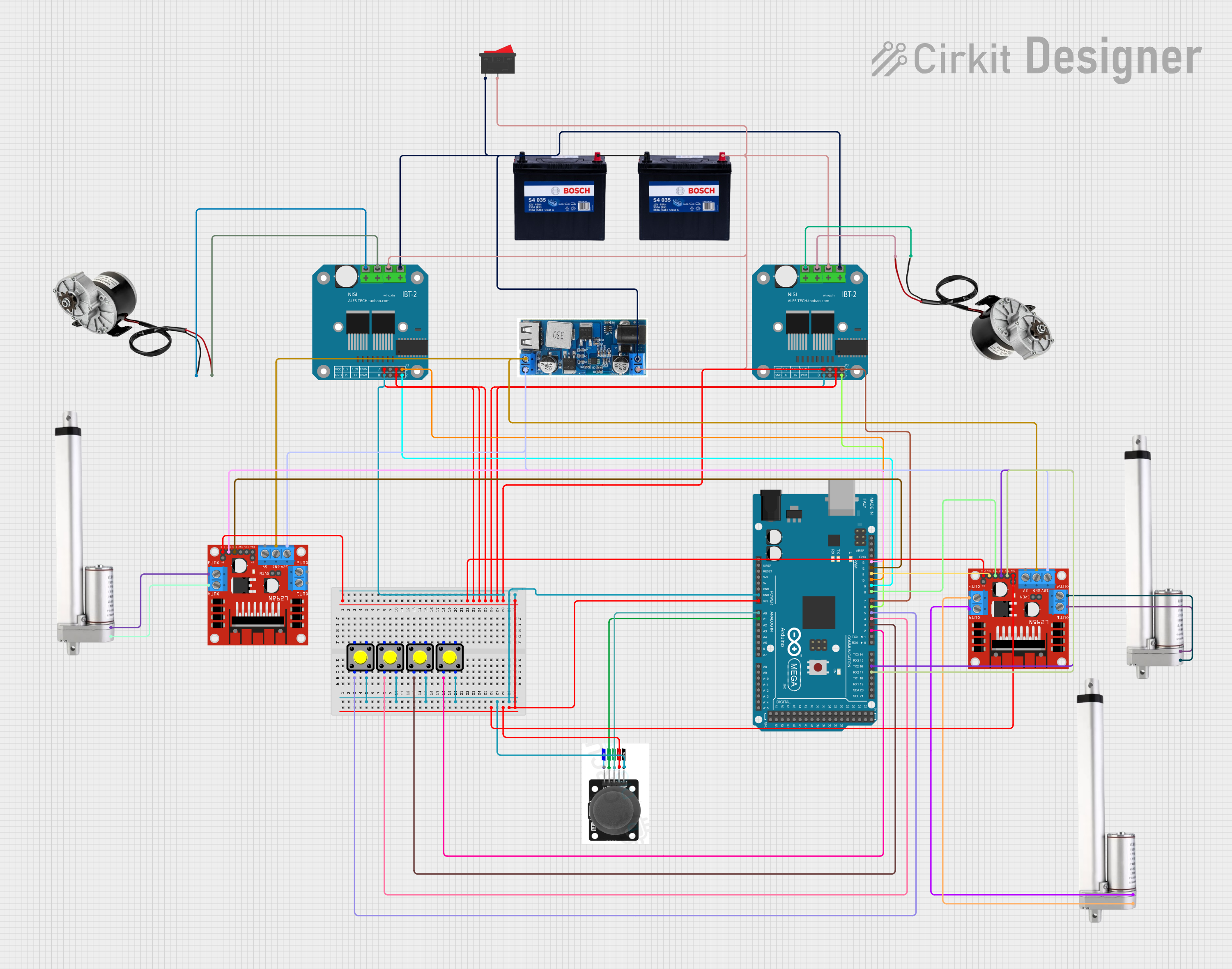
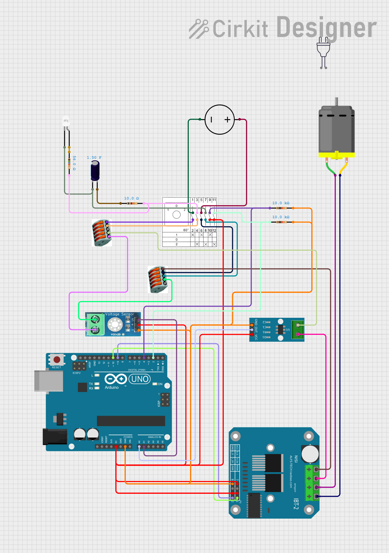

Explore Projects Built with Actuator Motor
Common Applications and Use Cases
- Robotics: Controlling robotic arms, grippers, and wheels.
- Industrial Automation: Operating conveyor belts, valves, and machinery.
- Automotive: Powering electric windows, seats, and mirrors.
- Home Automation: Adjusting blinds, doors, and smart furniture.
- Medical Devices: Driving pumps, prosthetics, and surgical tools.
Technical Specifications
The specifications of an actuator motor vary depending on its type and intended application. Below are general specifications for a typical DC actuator motor:
General Specifications
| Parameter | Value |
|---|---|
| Operating Voltage | 6V to 24V |
| Current Rating | 0.5A to 5A (depending on load) |
| Torque | 0.1 Nm to 10 Nm |
| Speed | 10 RPM to 5000 RPM |
| Power Rating | 1W to 100W |
| Motor Type | Brushed or Brushless DC |
| Operating Temperature | -20°C to 60°C |
Pin Configuration and Descriptions
| Pin Number | Pin Name | Description |
|---|---|---|
| 1 | VCC/Power | Positive power supply input (e.g., 12V). |
| 2 | GND | Ground connection. |
| 3 | Control Signal | Input for speed or direction control (PWM/logic). |
Note: The pin configuration may vary for different actuator motor models. Always refer to the datasheet of the specific motor you are using.
Usage Instructions
How to Use the Component in a Circuit
- Power Supply: Connect the VCC pin to a suitable power source (e.g., 12V) and the GND pin to the ground of the circuit.
- Control Signal: Use a microcontroller (e.g., Arduino UNO) or a motor driver to send control signals to the motor. For speed control, a PWM signal is typically used.
- Load Connection: Attach the mechanical load (e.g., a wheel or arm) to the motor shaft securely.
Important Considerations and Best Practices
- Voltage and Current Ratings: Ensure the power supply matches the motor's voltage and current requirements to avoid damage.
- Motor Driver: Use a motor driver (e.g., L298N or L293D) to interface the motor with a microcontroller, as direct connections may exceed the microcontroller's current limits.
- Heat Dissipation: Provide adequate ventilation or heat sinks if the motor operates under heavy loads for extended periods.
- Direction Control: Use an H-bridge circuit or motor driver to reverse the motor's direction.
- Noise Suppression: Add capacitors across the motor terminals to reduce electrical noise.
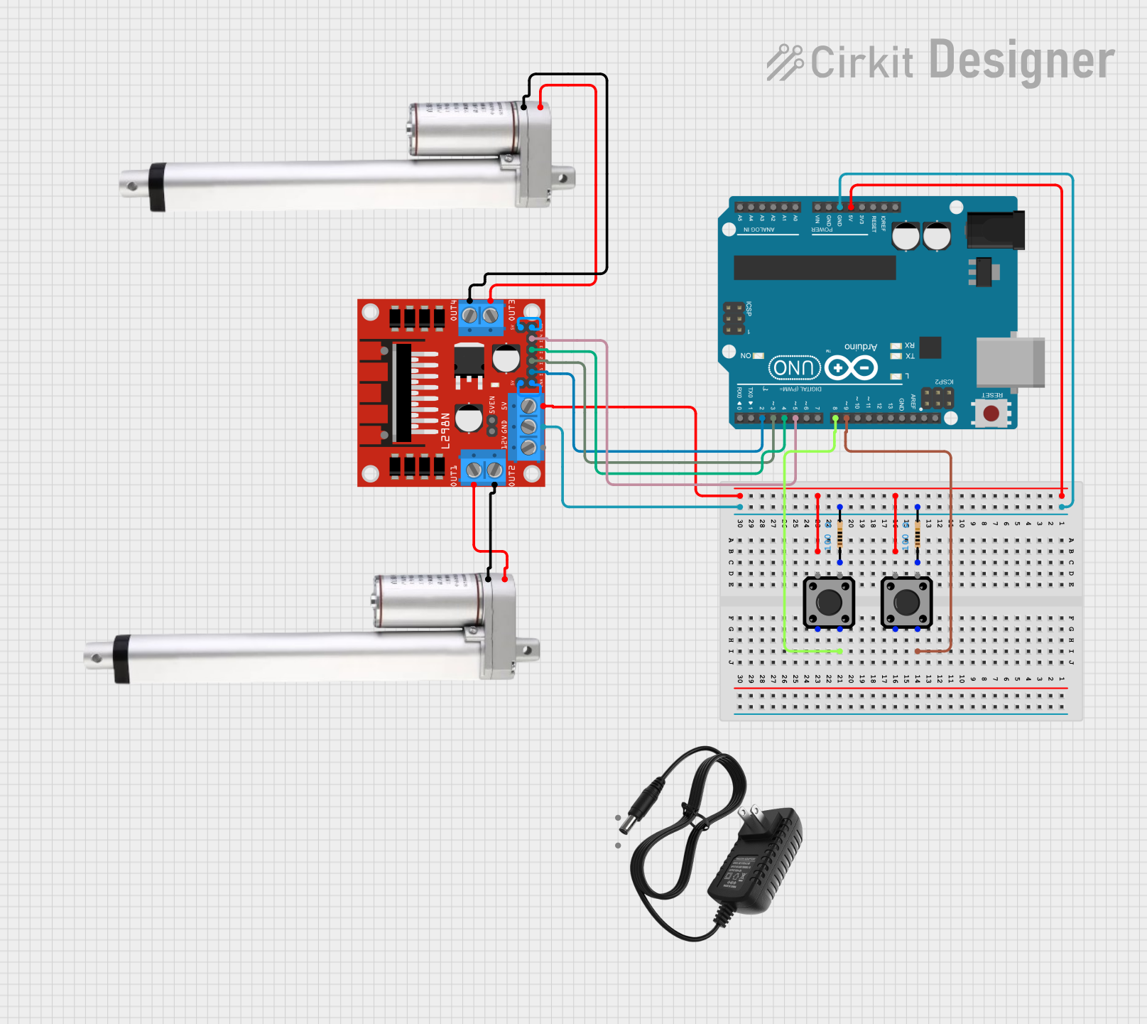
Example: Connecting an Actuator Motor to an Arduino UNO
Below is an example of controlling an actuator motor using an Arduino UNO and an L298N motor driver.
Circuit Connections
- Connect the motor's VCC and GND to the L298N motor driver's output terminals.
- Connect the L298N's input pins (IN1 and IN2) to Arduino digital pins 9 and 10.
- Connect the L298N's enable pin (EN) to Arduino digital pin 11 for PWM speed control.
- Power the L298N with a 12V power supply.
Arduino Code
// Define motor control pins
const int IN1 = 9;  // Motor direction control pin 1
const int IN2 = 10; // Motor direction control pin 2
const int EN = 11;  // Motor speed control (PWM) pin

void setup() {
  // Set motor control pins as outputs
  pinMode(IN1, OUTPUT);
  pinMode(IN2, OUTPUT);
  pinMode(EN, OUTPUT);
}

void loop() {
  // Rotate motor in one direction
  digitalWrite(IN1, HIGH); // Set IN1 high
  digitalWrite(IN2, LOW);  // Set IN2 low
  analogWrite(EN, 128);    // Set speed to 50% (PWM value: 128)

  delay(2000); // Run for 2 seconds

  // Stop the motor
  digitalWrite(IN1, LOW);
  digitalWrite(IN2, LOW);
  delay(1000); // Pause for 1 second

  // Rotate motor in the opposite direction
  digitalWrite(IN1, LOW);  // Set IN1 low
  digitalWrite(IN2, HIGH); // Set IN2 high
  analogWrite(EN, 128);    // Set speed to 50% (PWM value: 128)

  delay(2000); // Run for 2 seconds

  // Stop the motor
  digitalWrite(IN1, LOW);
  digitalWrite(IN2, LOW);
  delay(1000); // Pause for 1 second
}
Troubleshooting and FAQs
Common Issues and Solutions
Motor Does Not Spin
- Cause: Insufficient power supply or incorrect wiring.
- Solution: Verify the power supply voltage and current. Check all connections.
Motor Spins in the Wrong Direction
- Cause: Control signal polarity is reversed.
- Solution: Swap the IN1 and IN2 signals or adjust the control logic in the code.
Motor Overheats
- Cause: Excessive load or prolonged operation at high current.
- Solution: Reduce the load or provide better cooling.
Noisy Operation
- Cause: Electrical noise or mechanical issues.
- Solution: Add capacitors across motor terminals and inspect for mechanical faults.
PWM Control Not Working
- Cause: Incorrect PWM pin or frequency.
- Solution: Ensure the PWM pin is correctly defined in the code and the frequency matches the motor's requirements.
FAQs
Q: Can I connect the motor directly to an Arduino?
A: No, the Arduino cannot supply sufficient current. Use a motor driver.Q: How do I increase the motor's torque?
A: Use a gearbox or select a motor with a higher torque rating.Q: Can I use a 5V power supply for a 12V motor?
A: No, this will result in insufficient performance or failure to operate.Q: What is the difference between a DC motor and a stepper motor?
A: A DC motor provides continuous rotation, while a stepper motor moves in discrete steps for precise positioning.
By following this documentation, you can effectively integrate an actuator motor into your projects and troubleshoot common issues.