How to Use JST SM Female Connector 3 pin: Examples, Pinouts, and Specs
Introduction
The JST SM Female Connector 3 Pin is a compact and reliable connector designed for secure electrical connections in electronic circuits. It features a three-pin configuration, making it ideal for applications requiring multiple signal or power connections. Known for its durability and ease of use, this connector is widely used in LED lighting systems, robotics, drones, and other electronic projects where a robust and detachable connection is essential.
Explore Projects Built with JST SM Female Connector 3 pin


Explore Projects Built with JST SM Female Connector 3 pin
Common Applications and Use Cases
- LED strip connections
- Robotics and automation systems
- Drones and RC vehicles
- Power and signal connections in DIY electronics
- Audio and video equipment
Technical Specifications
The JST SM Female Connector 3 Pin is designed to provide a secure and stable connection. Below are its key technical details:
Key Technical Details
| Parameter | Specification |
|---|---|
| Number of Pins | 3 |
| Connector Type | Female |
| Rated Voltage | 250V AC/DC |
| Rated Current | 3A |
| Wire Gauge Compatibility | 22-28 AWG |
| Material | Nylon (housing), Copper (contacts) |
| Operating Temperature | -25°C to +85°C |
| Connector Pitch | 2.5mm |
Pin Configuration and Descriptions
| Pin Number | Description | Typical Use Case |
|---|---|---|
| 1 | Signal/Power (VCC) | Positive voltage or signal |
| 2 | Ground (GND) | Ground connection |
| 3 | Signal/Power (Data) | Data or secondary signal |
Usage Instructions
The JST SM Female Connector 3 Pin is straightforward to use and can be integrated into a variety of circuits. Follow the steps below to ensure proper usage:
How to Use the Connector
- Wire Preparation: Strip the insulation from the wires you intend to connect, exposing about 5mm of the conductor.
- Crimping: Use a crimping tool to attach the metal terminals to the stripped wires. Ensure a secure crimp for reliable connections.
- Insert Terminals: Insert the crimped terminals into the connector housing until they click into place.
- Mating the Connector: Align the JST SM Female Connector with its corresponding male connector and push them together until they lock securely.
Important Considerations and Best Practices
- Wire Gauge: Ensure the wires used are within the compatible range (22-28 AWG) for optimal performance.
- Polarity: Double-check the pin configuration to avoid reversing polarity, which could damage your circuit.
- Secure Connections: Use a proper crimping tool to ensure the terminals are firmly attached to the wires.
- Environmental Conditions: Avoid exposing the connector to extreme temperatures or moisture beyond its rated specifications.
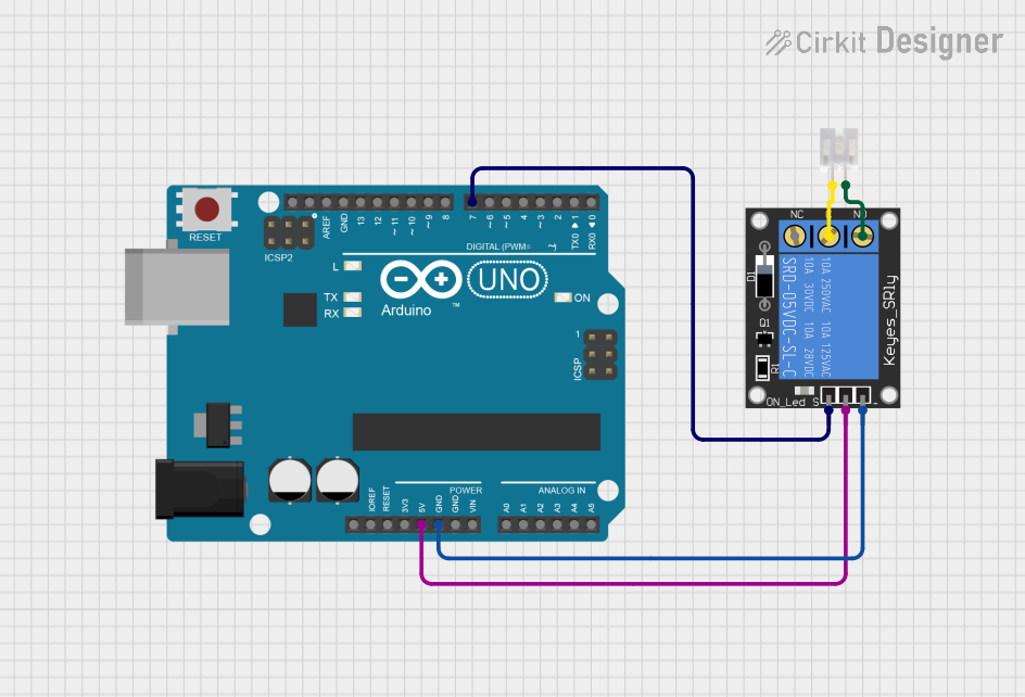
Example: Connecting to an Arduino UNO
The JST SM Female Connector 3 Pin can be used to connect peripherals like LED strips to an Arduino UNO. Below is an example of how to connect and control an LED strip:
Circuit Diagram
- Pin 1 (VCC) → Arduino 5V
- Pin 2 (GND) → Arduino GND
- Pin 3 (Data) → Arduino Digital Pin 6
Arduino Code
// Example code to control an LED strip using a JST SM 3-pin connector
#include <Adafruit_NeoPixel.h>

// Define the pin connected to the JST SM connector
#define LED_PIN 6

// Define the number of LEDs in the strip
#define NUM_LEDS 30

// Create a NeoPixel object
Adafruit_NeoPixel strip = Adafruit_NeoPixel(NUM_LEDS, LED_PIN, NEO_GRB + NEO_KHZ800);

void setup() {
  strip.begin(); // Initialize the LED strip
  strip.show();  // Turn off all LEDs initially
}

void loop() {
  // Example: Light up the LEDs in red
  for (int i = 0; i < NUM_LEDS; i++) {
    strip.setPixelColor(i, strip.Color(255, 0, 0)); // Set LED to red
    strip.show(); // Update the strip
    delay(50);    // Small delay for a cascading effect
  }
}
Troubleshooting and FAQs
Common Issues and Solutions
| Issue | Possible Cause | Solution |
|---|---|---|
| Connector does not lock securely | Misaligned or damaged terminals | Check alignment and inspect terminals |
| No power or signal transmission | Incorrect wiring or loose connection | Verify wiring and ensure secure crimp |
| Overheating of connector | Exceeding current rating | Ensure current is within 3A limit |
| Intermittent connection | Poor crimping or damaged wires | Re-crimp wires or replace damaged wires |
FAQs
Q1: Can I use this connector for high-power applications?
A1: The JST SM Female Connector 3 Pin is rated for a maximum current of 3A. For high-power applications, consider using a connector with a higher current rating.
Q2: How do I remove a terminal from the housing?
A2: Use a small flathead screwdriver or a terminal removal tool to gently press the locking tab inside the housing and pull the terminal out.
Q3: Is this connector waterproof?
A3: No, the JST SM Female Connector 3 Pin is not waterproof. For outdoor or moisture-prone environments, use a waterproof connector.
Q4: Can I use this connector with thicker wires?
A4: No, this connector is designed for wires in the 22-28 AWG range. Using thicker wires may damage the terminals or housing.
By following this documentation, you can effectively use the JST SM Female Connector 3 Pin in your electronic projects.