
How to Use Traffic Light: Examples, Pinouts, and Specs
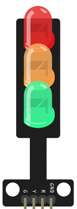
 Design with Traffic Light in Cirkit Designer
Introduction
A traffic light is a signaling device that uses colored lights—red, yellow, and green—to control traffic flow at intersections. The red light indicates "stop," the yellow light signals "caution" or "prepare to stop," and the green light allows vehicles to "go." Traffic lights are essential for maintaining order and safety on roads, ensuring smooth traffic flow, and reducing accidents.
Explore Projects Built with Traffic Light
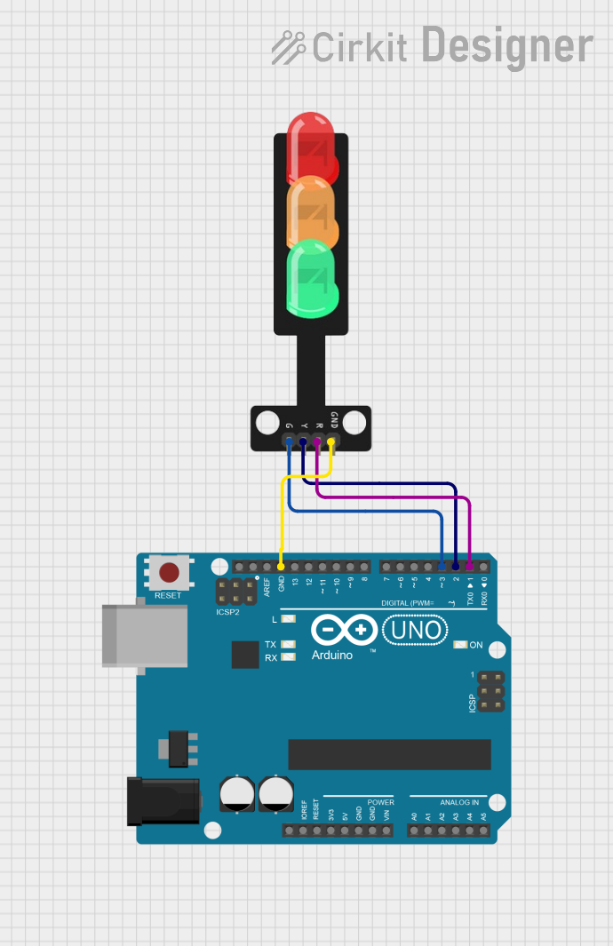 Open Project in Cirkit Designer
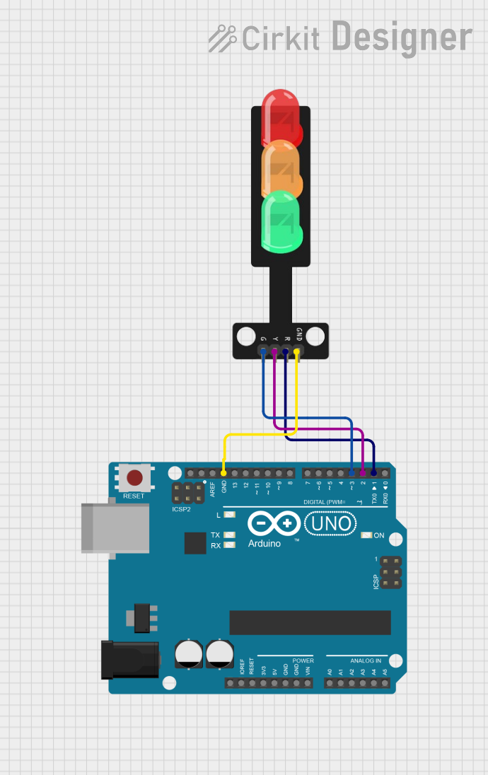 Open Project in Cirkit Designer
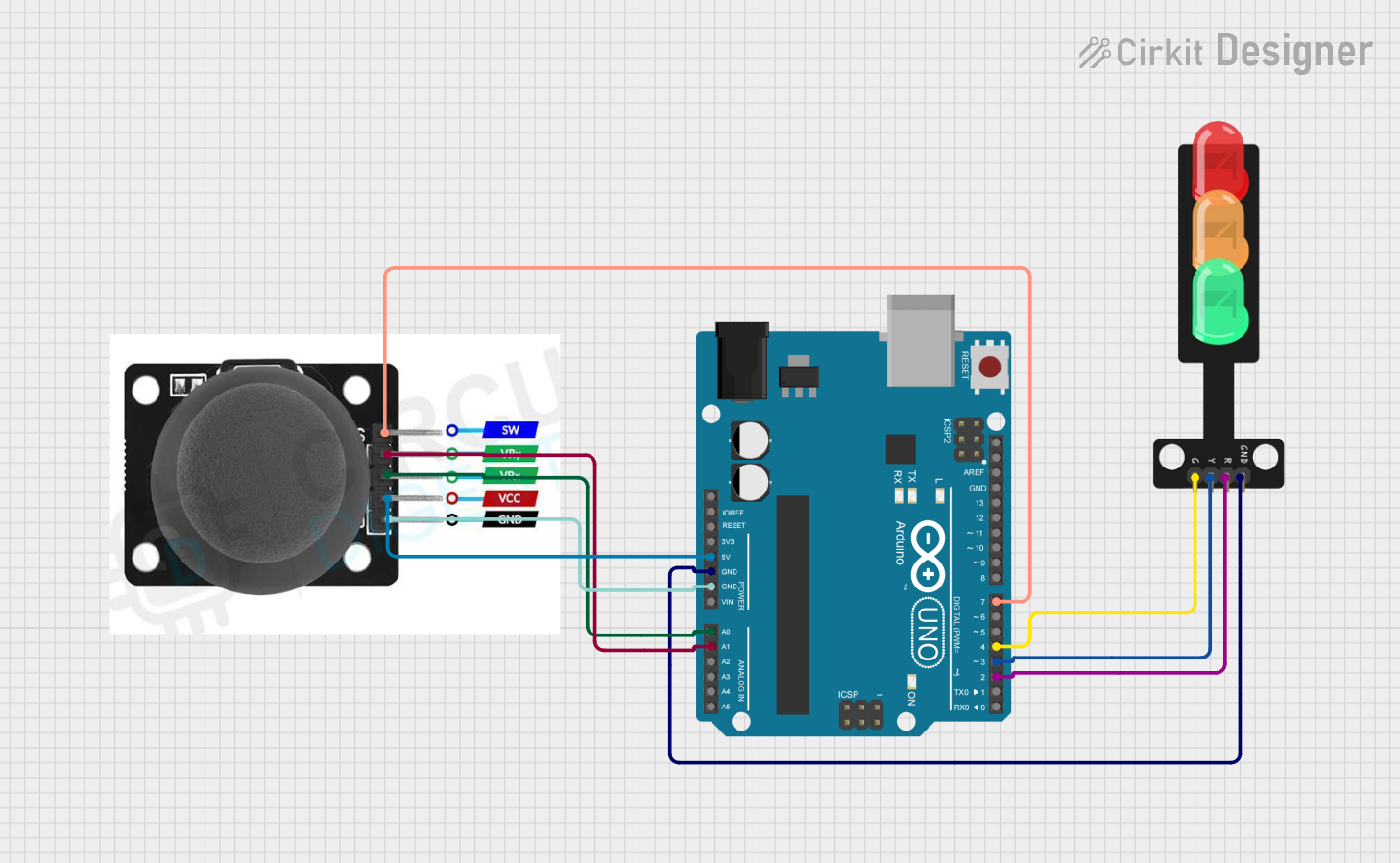 Open Project in Cirkit Designer
 Open Project in Cirkit Designer
Explore Projects Built with Traffic Light
Open Project in Cirkit DesignerOpen Project in Cirkit DesignerOpen Project in Cirkit DesignerOpen Project in Cirkit DesignerCommon Applications and Use Cases
- Traffic management at road intersections
- Pedestrian crossings
- Simulated traffic systems for educational purposes
- Embedded systems and IoT projects
- Robotics and automation projects
Technical Specifications
Below are the general specifications for a standard traffic light module used in electronics projects:
Key Technical Details
- Operating Voltage: 5V DC (common for modules)
- Current Consumption: ~20mA per LED
- LED Colors: Red, Yellow, Green
- Control Method: Individual control pins for each LED
- Dimensions: Varies by module (e.g., 30mm x 10mm for small modules)
- Mounting: PCB or breadboard compatible
Pin Configuration and Descriptions
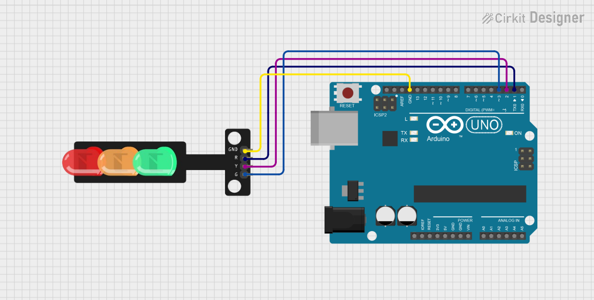
The traffic light module typically has 4 pins: one common cathode (ground) and three anodes for the LEDs. Below is the pin configuration:
| Pin | Name | Description |
|---|---|---|
| 1 | Red LED (+) | Connect to a digital output pin to control the red LED. |
| 2 | Yellow LED (+) | Connect to a digital output pin to control the yellow LED. |
| 3 | Green LED (+) | Connect to a digital output pin to control the green LED. |
| 4 | GND (-) | Common ground for all LEDs. |
Usage Instructions
How to Use the Component in a Circuit
- Power Supply: Connect the GND pin of the traffic light module to the ground of your power source or microcontroller.
- Control Pins: Connect the Red, Yellow, and Green LED pins to digital output pins of a microcontroller (e.g., Arduino UNO). Use current-limiting resistors (220Ω to 330Ω) in series with each LED to prevent damage.
- Programming: Write a program to control the LEDs based on the desired traffic light sequence.
Important Considerations and Best Practices
- Always use resistors to limit the current through the LEDs.
- Ensure the operating voltage does not exceed the module's specifications.
- Avoid prolonged activation of all LEDs simultaneously to prevent overheating.
- Test the module with a multimeter before integrating it into a larger circuit.
Example Code for Arduino UNO
Below is an example code to simulate a basic traffic light sequence using an Arduino UNO:
// Pin assignments for the traffic light module
const int redPin = 8;    // Red LED connected to digital pin 8
const int yellowPin = 9; // Yellow LED connected to digital pin 9
const int greenPin = 10; // Green LED connected to digital pin 10

void setup() {
  // Set the LED pins as outputs
  pinMode(redPin, OUTPUT);
  pinMode(yellowPin, OUTPUT);
  pinMode(greenPin, OUTPUT);
}

void loop() {
  // Red light ON for 5 seconds
  digitalWrite(redPin, HIGH);  // Turn on red LED
  digitalWrite(yellowPin, LOW); // Ensure yellow LED is off
  digitalWrite(greenPin, LOW);  // Ensure green LED is off
  delay(5000);                 // Wait for 5 seconds

  // Green light ON for 5 seconds
  digitalWrite(redPin, LOW);   // Turn off red LED
  digitalWrite(yellowPin, LOW); // Ensure yellow LED is off
  digitalWrite(greenPin, HIGH); // Turn on green LED
  delay(5000);                 // Wait for 5 seconds

  // Yellow light ON for 2 seconds
  digitalWrite(redPin, LOW);   // Ensure red LED is off
  digitalWrite(yellowPin, HIGH); // Turn on yellow LED
  digitalWrite(greenPin, LOW);  // Ensure green LED is off
  delay(2000);                 // Wait for 2 seconds
}
Troubleshooting and FAQs
Common Issues and Solutions
LEDs Not Lighting Up:
- Check the connections and ensure the GND pin is properly connected.
- Verify that the current-limiting resistors are correctly installed.
- Ensure the microcontroller pins are configured as outputs in the code.
Incorrect Light Sequence:
- Double-check the pin assignments in the code.
- Verify the logic in the program matches the desired sequence.
Dim LEDs:
- Ensure the power supply provides sufficient voltage and current.
- Check the resistor values; they may be too high.
Overheating LEDs:
- Reduce the duty cycle or use lower current-limiting resistor values.
FAQs
Q: Can I use this module with a 3.3V microcontroller?
A: Yes, but the brightness of the LEDs may be reduced. Ensure the resistors are adjusted accordingly.
Q: Do I need a separate power supply for the module?
A: No, the module can typically be powered directly from the microcontroller's 5V output.
Q: Can I control the traffic light module with a relay?
A: Yes, but it is more common to use a microcontroller for precise timing and control.
This documentation provides a comprehensive guide to using a traffic light module in electronic projects. Follow the instructions and best practices to ensure optimal performance and reliability.