How to Use MACH3 5 AXIS: Examples, Pinouts, and Specs
Introduction
The MACH3 5 AXIS by SIFA LAB is a versatile and powerful software solution designed for controlling CNC (Computer Numerical Control) machines. It enables precise movement and operation of up to five axes simultaneously, making it ideal for complex machining tasks such as milling, engraving, and 3D carving. This software is widely used in industrial, educational, and hobbyist applications due to its flexibility and compatibility with a variety of CNC hardware.
Explore Projects Built with MACH3 5 AXIS

Explore Projects Built with MACH3 5 AXIS
Common Applications and Use Cases
- Industrial Manufacturing: For precision machining of complex parts.
- Prototyping: Ideal for creating prototypes with intricate designs.
- Hobbyist CNC Projects: Used in DIY CNC machines for personal projects.
- Educational Purposes: Teaching CNC programming and machine operation.
- Engraving and 3D Carving: For artistic and decorative applications.
Technical Specifications
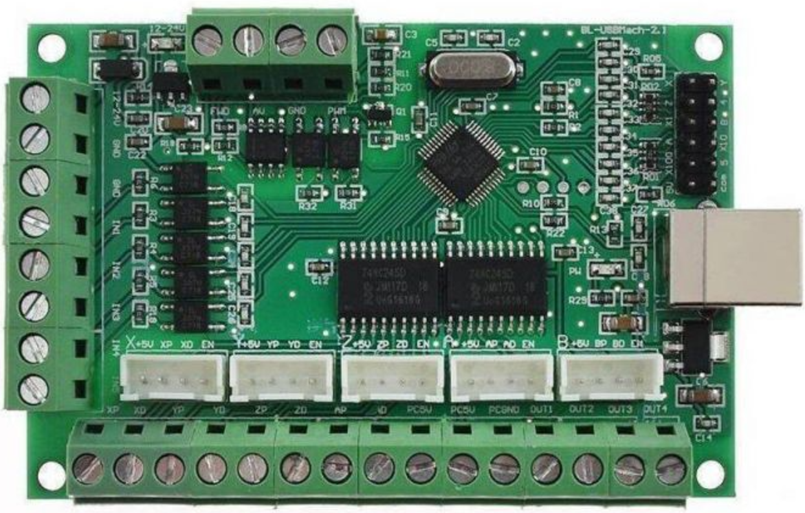
The MACH3 5 AXIS software works in conjunction with a breakout board and stepper motor drivers to control CNC machines. Below are the key technical details and pin configurations for a typical MACH3 5 AXIS breakout board.
Key Technical Details
- Manufacturer: SIFA LAB
- Control Axes: Up to 5 axes (X, Y, Z, A, B)
- Input Voltage: 5V DC (via USB or external power supply)
- Communication Interface: Parallel port (DB25) or USB (with adapter)
- Supported Stepper Drivers: Compatible with most stepper motor drivers (e.g., TB6600, DRV8825)
- Signal Type: TTL (Transistor-Transistor Logic)
- Maximum Pulse Frequency: 100 kHz
- Operating System Compatibility: Windows XP, Windows 7, Windows 10 (32-bit and 64-bit)
Pin Configuration and Descriptions
The MACH3 5 AXIS breakout board typically uses a DB25 parallel port for communication. Below is the pin configuration:
| Pin Number | Signal Name | Description |
|---|---|---|
| 1 | X Step | Step signal for the X-axis motor |
| 2 | X Direction | Direction signal for the X-axis motor |
| 3 | Y Step | Step signal for the Y-axis motor |
| 4 | Y Direction | Direction signal for the Y-axis motor |
| 5 | Z Step | Step signal for the Z-axis motor |
| 6 | Z Direction | Direction signal for the Z-axis motor |
| 7 | A Step | Step signal for the A-axis motor |
| 8 | A Direction | Direction signal for the A-axis motor |
| 9 | B Step | Step signal for the B-axis motor |
| 10 | Emergency Stop (E-Stop) | Input for emergency stop switch |
| 11 | Limit/Home Switch | Input for limit or home switches |
| 12 | Probe | Input for touch probe |
| 13 | Spindle Control | Output for spindle on/off control |
| 14 | Spindle PWM | Output for spindle speed control (PWM signal) |
| 15 | Coolant Control | Output for coolant on/off control |
| 16 | Enable | Enable signal for stepper drivers |
| 17 | Charge Pump | Safety signal to enable the breakout board |
| 18-25 | Ground (GND) | Common ground for all signals |
Usage Instructions
How to Use the MACH3 5 AXIS in a CNC System
Install the Software:
- Download the MACH3 software from the official SIFA LAB website or authorized distributor.
- Install the software on a compatible Windows PC.
- Configure the software to match your CNC machine's specifications.
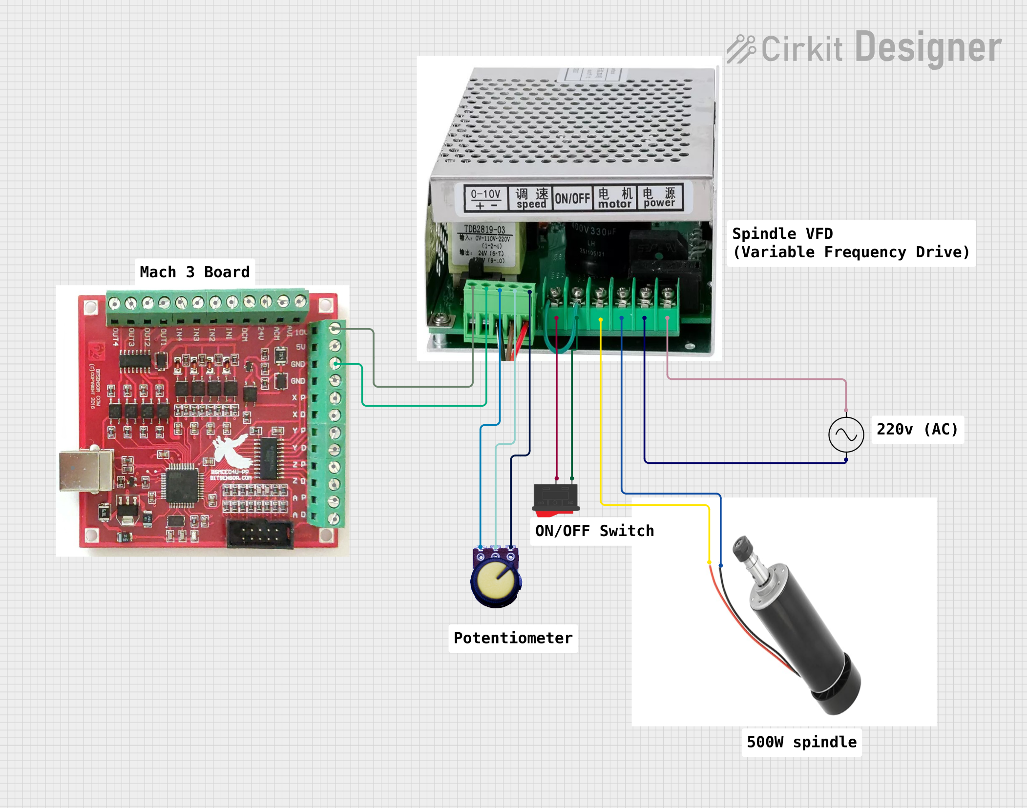
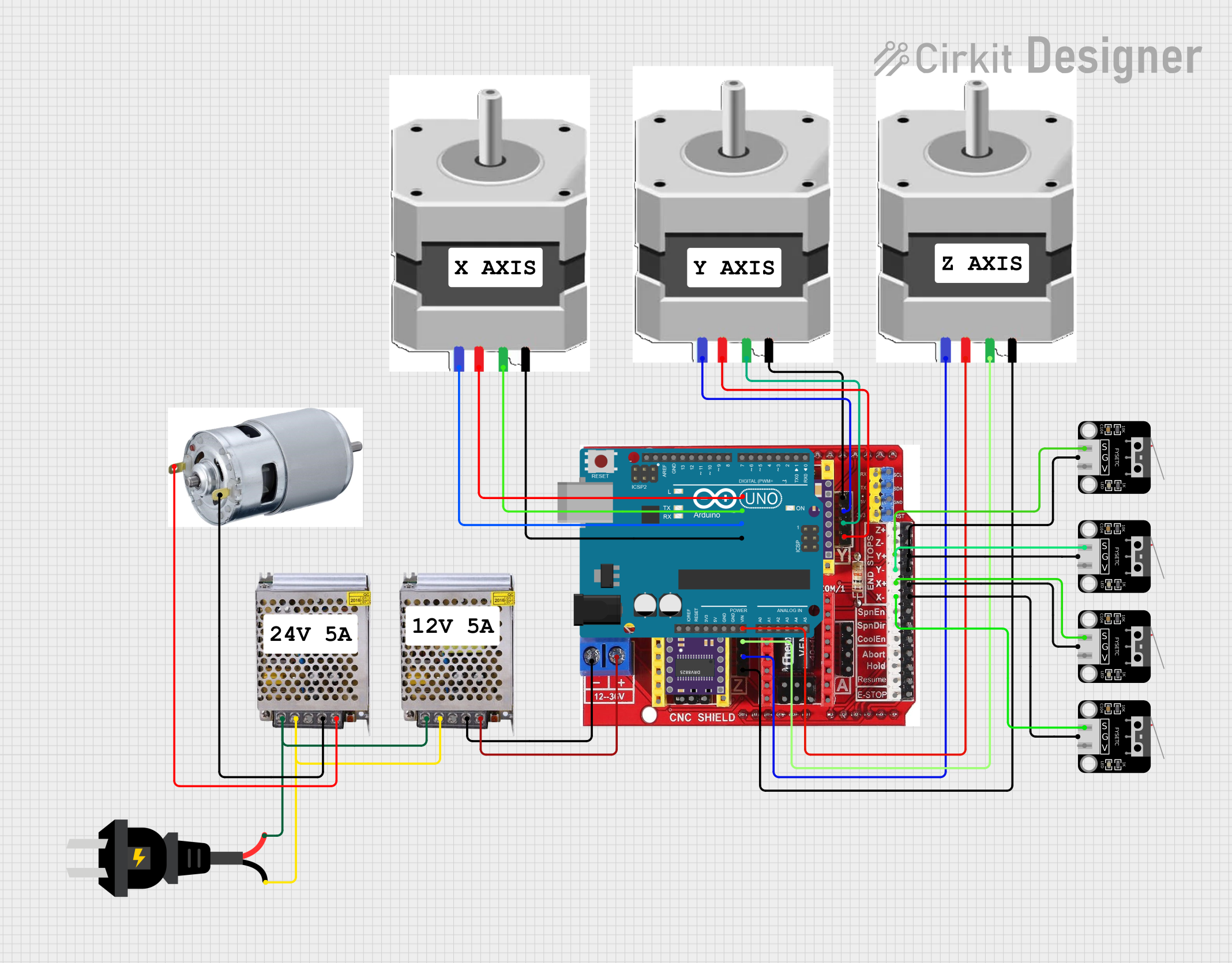
Connect the Breakout Board:
- Connect the MACH3 5 AXIS breakout board to your PC using a parallel port or USB adapter.
- Wire the stepper motor drivers, limit switches, and other peripherals to the breakout board according to the pin configuration.
Configure the MACH3 Software:
- Open the MACH3 software and navigate to the "Ports and Pins" settings.
- Assign the correct pin numbers for each axis, limit switch, and other inputs/outputs.
- Set the step and direction pulse width to match your stepper drivers.
Test the System:
- Use the MACH3 software's jog controls to test the movement of each axis.
- Verify that the limit switches and emergency stop function correctly.
Load and Run G-Code:
- Import your G-code file into the MACH3 software.
- Simulate the toolpath to ensure accuracy.
- Start the machining process and monitor the operation.
Important Considerations and Best Practices
- Power Supply: Ensure the breakout board and stepper drivers are powered with the correct voltage and current.
- Grounding: Properly ground all components to prevent electrical noise and interference.
- Emergency Stop: Always connect and test the emergency stop switch for safety.
- Backup Configuration: Save a backup of your MACH3 configuration settings for future use.
- Driver Compatibility: Verify that your stepper drivers are compatible with the MACH3 5 AXIS breakout board.
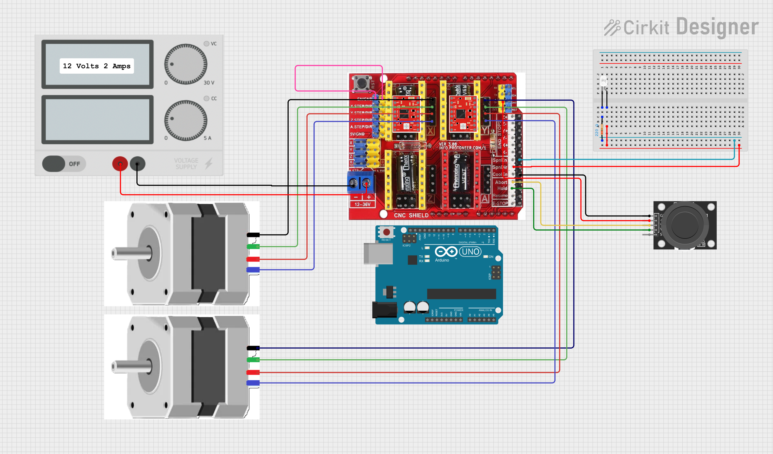
Example Code for Arduino UNO Integration
While the MACH3 5 AXIS is primarily used with PCs, you can use an Arduino UNO to simulate step and direction signals for testing purposes. Below is an example code snippet:
// Arduino code to generate step and direction signals for testing MACH3 5 AXIS
const int stepPin = 2;  // Pin connected to Step signal
const int dirPin = 3;   // Pin connected to Direction signal
const int stepsPerRevolution = 200; // Steps per revolution for the stepper motor

void setup() {
  pinMode(stepPin, OUTPUT); // Set step pin as output
  pinMode(dirPin, OUTPUT);  // Set direction pin as output
  digitalWrite(dirPin, HIGH); // Set initial direction
}

void loop() {
  // Generate step pulses
  for (int i = 0; i < stepsPerRevolution; i++) {
    digitalWrite(stepPin, HIGH); // Step pulse high
    delayMicroseconds(500);      // Pulse width (500 µs)
    digitalWrite(stepPin, LOW);  // Step pulse low
    delayMicroseconds(500);      // Pulse interval (500 µs)
  }
  delay(1000); // Wait 1 second before changing direction

  // Change direction
  digitalWrite(dirPin, !digitalRead(dirPin)); // Toggle direction
}
Troubleshooting and FAQs
Common Issues and Solutions
No Movement on One or More Axes:
- Cause: Incorrect pin configuration or wiring.
- Solution: Double-check the pin assignments in the MACH3 software and verify the wiring.
Stepper Motors Vibrate but Do Not Rotate:
- Cause: Incorrect step pulse width or insufficient power supply.
- Solution: Adjust the step pulse width in the MACH3 settings and ensure the power supply meets the requirements.
Limit Switches Not Detected:
- Cause: Faulty wiring or incorrect pin assignment.
- Solution: Verify the wiring and ensure the correct pins are assigned in the MACH3 software.
Spindle Does Not Start:
- Cause: Incorrect spindle control configuration.
- Solution: Check the spindle control settings in the MACH3 software and verify the wiring.
Software Crashes or Freezes:
- Cause: Incompatible operating system or hardware.
- Solution: Ensure the PC meets the system requirements and update the MACH3 software.
FAQs
Q: Can I use MACH3 5 AXIS with a USB connection?
- A: Yes, but you will need a USB-to-parallel adapter or a USB motion controller compatible with MACH3.
Q: Is MACH3 5 AXIS compatible with Linux?
- A: No, MACH3 is designed for Windows operating systems only.
Q: Can I control more than five axes with MACH3?
- A: No, the MACH3 5 AXIS is limited to controlling up to five axes simultaneously.
Q: How do I update the MACH3 software?
- A: Visit the official SIFA LAB website to download the latest version and follow the installation instructions.
Q: What file formats does MACH3 support for G-code?
- A: MACH3 supports standard G-code files with extensions such as
.nc,.tap, and.txt.
- A: MACH3 supports standard G-code files with extensions such as