How to Use Orange Pi 3B: Examples, Pinouts, and Specs
Introduction
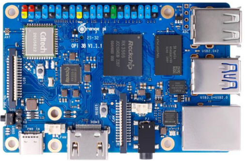
The Orange Pi 3B is a powerful and versatile single-board computer (SBC) developed by Orange Pi, Shenzhen Xunlong Software Co., Ltd. It is equipped with a quad-core ARM Cortex-A53 processor, up to 2GB of RAM, and supports multiple operating systems, including Android and Linux. This board is designed for a variety of applications, such as media centers, IoT devices, educational tools, and lightweight servers.
With its compact size and rich connectivity options, including HDMI, USB, Ethernet, and GPIO pins, the Orange Pi 3B is an excellent choice for hobbyists, developers, and professionals looking to build innovative projects.
Explore Projects Built with Orange Pi 3B


Explore Projects Built with Orange Pi 3B
Common Applications
- Media Centers: Stream and play high-definition video content.
- IoT Projects: Serve as a hub for smart devices or sensors.
- Educational Tools: Teach programming, electronics, and system design.
- Home Automation: Control and monitor home appliances.
- Lightweight Servers: Host small-scale web servers or file-sharing systems.
Technical Specifications
Key Technical Details
| Specification | Details |
|---|---|
| Processor | Allwinner H6 Quad-Core ARM Cortex-A53 |
| GPU | Mali-T720 MP2 |
| RAM | 1GB or 2GB DDR3 (depending on the model) |
| Storage | microSD card slot, eMMC module support (up to 16GB) |
| Operating Systems | Android, Ubuntu, Debian, and other Linux distributions |
| Connectivity | HDMI 2.0, USB 3.0, USB 2.0, Gigabit Ethernet, Wi-Fi, Bluetooth |
| GPIO | 26-pin GPIO header for interfacing with external devices |
| Power Supply | 5V/3A via USB Type-C |
| Dimensions | 90mm x 64mm |
Pin Configuration and Descriptions
The Orange Pi 3B features a 26-pin GPIO header for interfacing with external devices. Below is the pinout description:
| Pin Number | Pin Name | Description |
|---|---|---|
| 1 | 3.3V | Power supply (3.3V) |
| 2 | 5V | Power supply (5V) |
| 3 | GPIO2 | General-purpose I/O |
| 4 | 5V | Power supply (5V) |
| 5 | GPIO3 | General-purpose I/O |
| 6 | GND | Ground |
| 7 | GPIO4 | General-purpose I/O |
| 8 | GPIO14 | UART TX |
| 9 | GND | Ground |
| 10 | GPIO15 | UART RX |
| 11 | GPIO17 | General-purpose I/O |
| 12 | GPIO18 | General-purpose I/O |
| 13 | GPIO27 | General-purpose I/O |
| 14 | GND | Ground |
| 15 | GPIO22 | General-purpose I/O |
| 16 | GPIO23 | General-purpose I/O |
| 17 | 3.3V | Power supply (3.3V) |
| 18 | GPIO24 | General-purpose I/O |
| 19 | GPIO10 | SPI MOSI |
| 20 | GND | Ground |
| 21 | GPIO9 | SPI MISO |
| 22 | GPIO25 | General-purpose I/O |
| 23 | GPIO11 | SPI CLK |
| 24 | GPIO8 | SPI CS0 |
| 25 | GND | Ground |
| 26 | GPIO7 | SPI CS1 |
Usage Instructions
How to Use the Orange Pi 3B in a Circuit
Powering the Board:
- Use a 5V/3A power adapter with a USB Type-C connector to power the Orange Pi 3B.
- Ensure the power supply is stable to avoid damage to the board.
Connecting Peripherals:
- Attach a monitor via the HDMI port for video output.
- Connect a keyboard and mouse to the USB ports for input.
- Use the Ethernet port or Wi-Fi for network connectivity.
Installing an Operating System:
- Download a compatible OS image (e.g., Ubuntu or Android) from the official Orange Pi website.
- Flash the image onto a microSD card using tools like Etcher or Rufus.
- Insert the microSD card into the board and power it on.
Using GPIO Pins:
- Connect external devices (e.g., LEDs, sensors) to the GPIO header.
- Use libraries like RPi.GPIO (Python) or WiringPi (C++) to control the GPIO pins.
Example: Blinking an LED with Python
Below is an example of how to blink an LED connected to GPIO17 (pin 11) using Python:
Import the required library
import RPi.GPIO as GPIO import time
Set up GPIO mode
GPIO.setmode(GPIO.BCM) # Use Broadcom pin numbering GPIO.setwarnings(False)
Define the GPIO pin for the LED
LED_PIN = 17
Set up the LED pin as an output
GPIO.setup(LED_PIN, GPIO.OUT)
Blink the LED in a loop
try: while True: GPIO.output(LED_PIN, GPIO.HIGH) # Turn LED on time.sleep(1) # Wait for 1 second GPIO.output(LED_PIN, GPIO.LOW) # Turn LED off time.sleep(1) # Wait for 1 second except KeyboardInterrupt: # Clean up GPIO settings on exit GPIO.cleanup()
Important Considerations
- Ensure the GPIO pins are not overloaded with current. Use resistors where necessary.
- Avoid short circuits by double-checking connections.
- Use a heatsink or fan for cooling during intensive tasks to prevent overheating.
Troubleshooting and FAQs
Common Issues and Solutions
The board does not power on:
- Ensure the power adapter provides 5V/3A and is properly connected.
- Check the USB Type-C cable for damage or loose connections.
No display on the monitor:
- Verify the HDMI cable is securely connected to both the board and the monitor.
- Ensure the monitor is set to the correct input source.
- Reflash the OS image on the microSD card if the issue persists.
Wi-Fi or Bluetooth not working:
- Check if the drivers for Wi-Fi and Bluetooth are installed in the OS.
- Ensure the board is within range of the Wi-Fi router or Bluetooth device.
GPIO pins not responding:
- Confirm the correct pin numbering scheme (BCM or BOARD) is used in the code.
- Check for loose or incorrect connections to external devices.
FAQs
Q: Can I power the Orange Pi 3B via GPIO pins?
A: No, it is recommended to use the USB Type-C port for stable power delivery.Q: What is the maximum resolution supported by the HDMI port?
A: The HDMI 2.0 port supports up to 4K resolution at 60Hz.Q: Can I use the Orange Pi 3B for gaming?
A: While it can handle lightweight games, it is not designed for high-performance gaming.Q: How do I update the firmware?
A: Download the latest firmware from the official Orange Pi website and follow the update instructions provided.
This documentation provides a comprehensive guide to using the Orange Pi 3B effectively. For further assistance, refer to the official Orange Pi forums and support channels.