How to Use Teensy: Examples, Pinouts, and Specs
Introduction
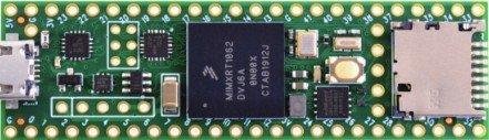
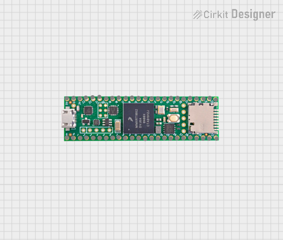
The Teensy is a small, USB-based microcontroller development board manufactured by PJRC. It is designed for easy programming and seamless integration into a wide range of projects. Teensy boards are compatible with the Arduino IDE, making them accessible to both beginners and experienced developers. With their compact size, powerful processing capabilities, and extensive I/O options, Teensy boards are ideal for applications such as robotics, audio processing, sensor interfacing, and more.
Explore Projects Built with Teensy
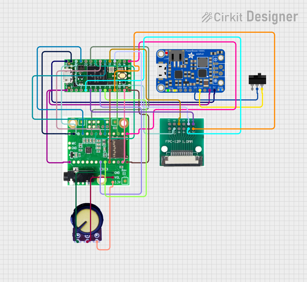
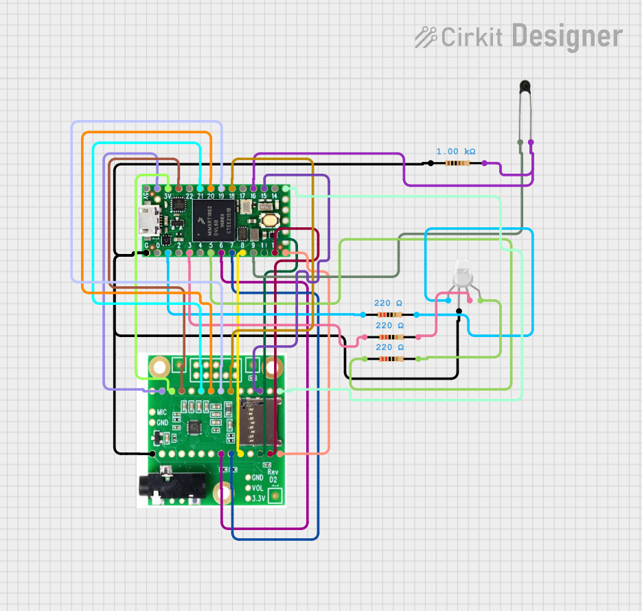
Explore Projects Built with Teensy
Common Applications
- Robotics and automation systems
- Audio signal processing and synthesis
- Sensor data acquisition and control
- Wearable electronics
- Internet of Things (IoT) devices
- LED lighting and display control
Technical Specifications
The Teensy family includes several models, such as the Teensy 4.0, Teensy 4.1, and Teensy LC. Below are the general technical specifications for the Teensy 4.0, one of the most popular models:
Key Technical Details
- Microcontroller: NXP i.MX RT1062 (ARM Cortex-M7, 32-bit)
- Clock Speed: 600 MHz
- Flash Memory: 2 MB
- RAM: 1 MB
- EEPROM: 4 KB (emulated)
- Operating Voltage: 3.3V (5V tolerant inputs)
- USB Interface: USB 2.0, full-speed (12 Mbps)
- Digital I/O Pins: 40 (all 5V tolerant)
- Analog Input Pins: 14 (12-bit resolution)
- PWM Pins: 31
- Communication Protocols: UART, SPI, I2C, CAN, I2S
- Dimensions: 1.4 x 0.7 inches (35.56 x 17.78 mm)
Pin Configuration and Descriptions
The Teensy 4.0 features a compact pin layout. Below is a table describing the pin configuration:
| Pin | Function | Description |
|---|---|---|
| VIN | Power Input | Connect to 5V power source (regulated to 3.3V internally). |
| GND | Ground | Common ground for the circuit. |
| 3.3V | Power Output | Provides 3.3V output for external components. |
| A0-A13 | Analog Inputs | 12-bit ADC pins for reading analog signals. |
| D0-D39 | Digital I/O | General-purpose digital input/output pins. |
| TX/RX | UART Communication | Serial communication pins (TX for transmit, RX for receive). |
| SCL/SDA | I2C Communication | Clock (SCL) and data (SDA) lines for I2C communication. |
| MOSI | SPI Communication | Master Out Slave In pin for SPI communication. |
| MISO | SPI Communication | Master In Slave Out pin for SPI communication. |
| SCK | SPI Communication | Clock pin for SPI communication. |
| CANRX | CAN Bus Receive | Receive pin for CAN bus communication. |
| CANTX | CAN Bus Transmit | Transmit pin for CAN bus communication. |
| RESET | Reset | Resets the microcontroller. |
Usage Instructions
How to Use the Teensy in a Circuit
Powering the Teensy:
- Connect the VIN pin to a 5V power source or use the USB port for power and programming.
- Ensure the GND pin is connected to the ground of your circuit.
Programming the Teensy:
- Install the Arduino IDE and the Teensyduino add-on from the PJRC website.
- Select the appropriate Teensy model from the "Tools" menu in the Arduino IDE.
- Write your code and upload it to the Teensy via the USB connection.
Connecting Peripherals:
- Use the digital I/O pins for controlling LEDs, relays, or other digital devices.
- Use the analog input pins to read sensor data.
- Utilize communication protocols (UART, SPI, I2C) for interfacing with external modules.
Important Considerations
- Voltage Levels: The Teensy operates at 3.3V logic levels. While its inputs are 5V tolerant, ensure that connected peripherals are compatible with 3.3V outputs.
- Heat Management: At high clock speeds (e.g., 600 MHz), the Teensy may generate heat. Ensure proper ventilation or consider reducing the clock speed if overheating occurs.
- Bootloader: The Teensy includes a pre-installed bootloader, so no external programmer is required.
Example Code for Arduino IDE
The following example demonstrates how to blink an LED connected to pin 13:
// Blink an LED connected to pin 13 on the Teensy board

void setup() {
  pinMode(13, OUTPUT); // Set pin 13 as an output
}

void loop() {
  digitalWrite(13, HIGH); // Turn the LED on
  delay(1000);            // Wait for 1 second
  digitalWrite(13, LOW);  // Turn the LED off
  delay(1000);            // Wait for 1 second
}
Troubleshooting and FAQs
Common Issues and Solutions
Teensy Not Recognized by the Computer:
- Ensure the USB cable is functional and supports data transfer (not just charging).
- Verify that the Teensyduino add-on is installed correctly.
- Press the reset button on the Teensy to reinitialize the USB connection.
Code Upload Fails:
- Check that the correct Teensy model is selected in the Arduino IDE.
- Ensure no other program is using the USB port.
- Try using a different USB port or cable.
Overheating:
- Reduce the clock speed in the Arduino IDE under "Tools > CPU Speed".
- Avoid running high-power peripherals directly from the Teensy.
Analog Readings Are Inaccurate:
- Use proper grounding and shielding for analog sensors.
- Add a capacitor between the analog input pin and ground to reduce noise.
FAQs
Q: Can I use the Teensy with 5V sensors?
A: Yes, the Teensy's inputs are 5V tolerant, but its outputs operate at 3.3V. Use a level shifter if the sensor requires 5V logic levels.
Q: How do I reset the Teensy?
A: Press the reset button on the board. This will restart the microcontroller without erasing the uploaded program.
Q: Can I use the Teensy for audio processing?
A: Absolutely! The Teensy is well-suited for audio applications, and PJRC provides an Audio Library for advanced audio processing and synthesis.
Q: Is the Teensy compatible with Arduino shields?
A: The Teensy is not directly compatible with standard Arduino shields due to its smaller size and different pin layout. However, adapter boards are available for certain shields.