How to Use dm556: Examples, Pinouts, and Specs
Introduction
The DM556 is a dual precision timer IC designed for generating accurate time delays and oscillations. It features two independent timing circuits, making it highly versatile for applications requiring precise timing and pulse generation. The DM556 is widely used in various electronic circuits, including oscillators, pulse-width modulation (PWM) circuits, and time delay generators.
Explore Projects Built with dm556


Explore Projects Built with dm556
Common Applications and Use Cases
- Monostable (one-shot) and astable (oscillating) multivibrators
- Pulse-width modulation (PWM) circuits
- Time delay generation
- Frequency generation and measurement
- Sequential timing circuits
- LED flashers and light controllers
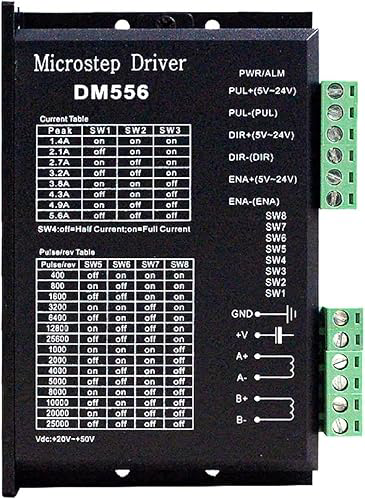
Technical Specifications
The DM556 is a robust and reliable timer IC with the following key specifications:
| Parameter | Value |
|---|---|
| Supply Voltage (Vcc) | 4.5V to 16V |
| Supply Current | 10mA (typical) |
| Output Voltage (High) | Vcc - 1.5V (typical) |
| Output Voltage (Low) | 0.1V (typical) |
| Timing Accuracy | ±1% |
| Operating Temperature | -40°C to +85°C |
| Package Type | DIP-14, SOIC-14 |
Pin Configuration and Descriptions
The DM556 comes in a 14-pin package. Below is the pinout and description:
| Pin Number | Pin Name | Description |
|---|---|---|
| 1 | GND | Ground pin for the IC |
| 2 | TRIG1 | Trigger input for Timer 1 |
| 3 | OUT1 | Output of Timer 1 |
| 4 | RESET1 | Reset input for Timer 1 (active low) |
| 5 | CTRL1 | Control voltage input for Timer 1 |
| 6 | THRES1 | Threshold input for Timer 1 |
| 7 | DISCH1 | Discharge pin for Timer 1 |
| 8 | VCC | Positive supply voltage |
| 9 | DISCH2 | Discharge pin for Timer 2 |
| 10 | THRES2 | Threshold input for Timer 2 |
| 11 | CTRL2 | Control voltage input for Timer 2 |
| 12 | RESET2 | Reset input for Timer 2 (active low) |
| 13 | OUT2 | Output of Timer 2 |
| 14 | TRIG2 | Trigger input for Timer 2 |
Usage Instructions
The DM556 can be used in both monostable and astable configurations. Below are the steps and considerations for using the component effectively:
Monostable Mode (One-Shot Timer)
- Connect a resistor (R) and capacitor (C) to the
THRESandDISCHpins to set the desired time delay. - Apply a trigger pulse to the
TRIGpin. The output will go high for a duration determined by the RC time constant. - Use the
RESETpin to terminate the timing cycle prematurely if needed (active low).
Astable Mode (Oscillator)
- Connect a resistor (R1) between
VCCandDISCH, and another resistor (R2) betweenDISCHandTHRES. - Connect a capacitor (C) between
THRESand GND. - The output will oscillate between high and low states, with the frequency determined by the values of R1, R2, and C.
Important Considerations
- Ensure the supply voltage (Vcc) is within the specified range (4.5V to 16V).
- Use decoupling capacitors (e.g., 0.1µF) near the Vcc pin to reduce noise and improve stability.
- Avoid leaving unused pins floating; connect them to appropriate logic levels or ground.
- For precise timing, use high-quality resistors and capacitors with low tolerances.
Example: Using DM556 with Arduino UNO
The DM556 can be used with an Arduino UNO to generate precise timing signals. Below is an example of interfacing the DM556 in astable mode:
Circuit Connections
- Connect
VCCto the 5V pin of the Arduino. - Connect
GNDto the GND pin of the Arduino. - Connect the
OUT1pin to a digital input pin on the Arduino (e.g., D2). - Configure the timing components (R1, R2, and C) as per the desired frequency.
Arduino Code
// Example code to read the DM556 output and toggle an LED
const int dm556OutputPin = 2; // DM556 OUT1 connected to Arduino pin 2
const int ledPin = 13;        // Onboard LED pin

void setup() {
  pinMode(dm556OutputPin, INPUT); // Set DM556 output pin as input
  pinMode(ledPin, OUTPUT);        // Set LED pin as output
}

void loop() {
  int signal = digitalRead(dm556OutputPin); // Read the DM556 output signal
  digitalWrite(ledPin, signal);             // Toggle LED based on DM556 output
}
Troubleshooting and FAQs
Common Issues
No Output Signal
- Ensure the supply voltage is within the specified range (4.5V to 16V).
- Verify the connections of the timing components (R and C).
- Check if the
RESETpin is held high; a low signal will disable the output.
Inaccurate Timing
- Use resistors and capacitors with low tolerances for better accuracy.
- Ensure the control voltage pin (
CTRL) is properly connected or left floating (default behavior).
Output Stuck High or Low
- Verify the trigger signal is correctly applied to the
TRIGpin. - Check for short circuits or incorrect wiring.
- Verify the trigger signal is correctly applied to the
FAQs
Q: Can the DM556 operate at 3.3V?
A: No, the minimum supply voltage for the DM556 is 4.5V. Operating below this voltage may result in erratic behavior.
Q: How do I calculate the frequency in astable mode?
A: The frequency is determined by the formula:
[
f = \frac{1.44}{(R1 + 2R2) \cdot C}
]
where R1, R2 are resistors, and C is the capacitor.
Q: Can I use the DM556 for PWM applications?
A: Yes, the DM556 can be configured in astable mode to generate PWM signals by adjusting the duty cycle using R1, R2, and C.
By following this documentation, you can effectively use the DM556 in your electronic projects for precise timing and pulse generation.