
How to Use Servo: Examples, Pinouts, and Specs
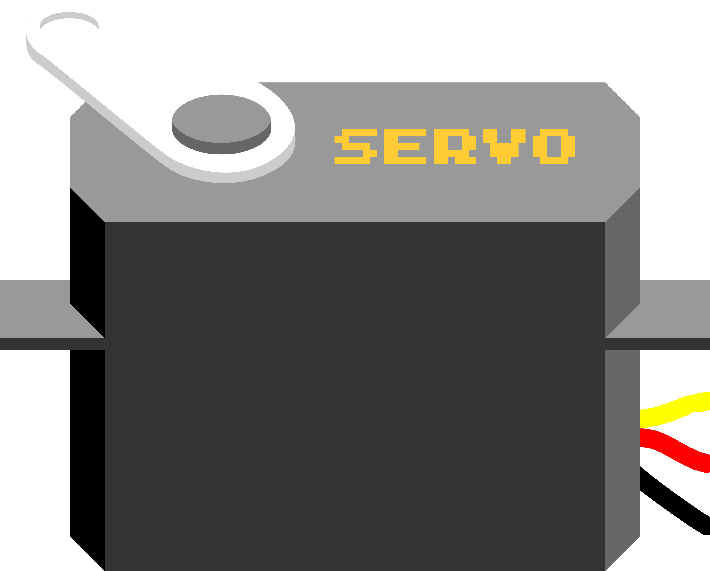
 Design with Servo in Cirkit Designer
Introduction
A servo is a rotary actuator that allows for precise control of angular position, velocity, and acceleration. It consists of a motor coupled to a sensor for position feedback, along with a control circuit. Servos are widely used in robotics, automation, remote-controlled vehicles, and other applications requiring precise motion control. Their ability to move to a specific angle and hold that position makes them ideal for tasks such as steering mechanisms, robotic arms, and pan-tilt camera systems.
Explore Projects Built with Servo
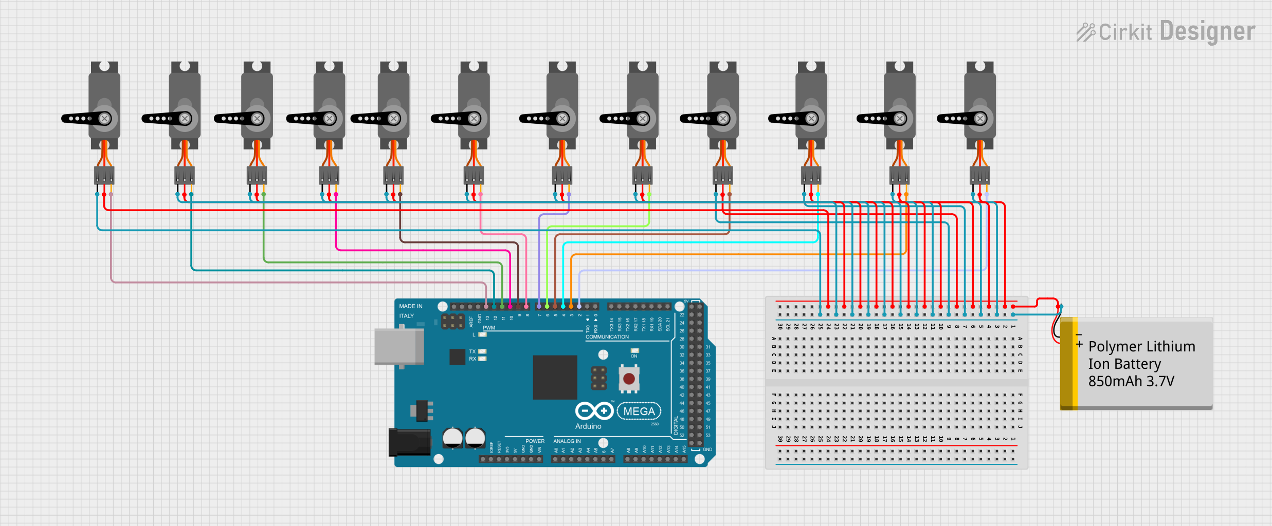 Open Project in Cirkit Designer
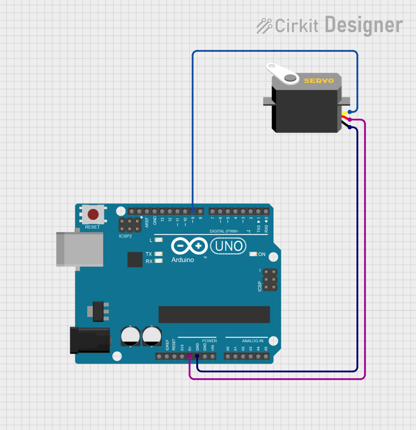 Open Project in Cirkit Designer
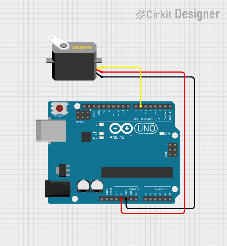 Open Project in Cirkit Designer
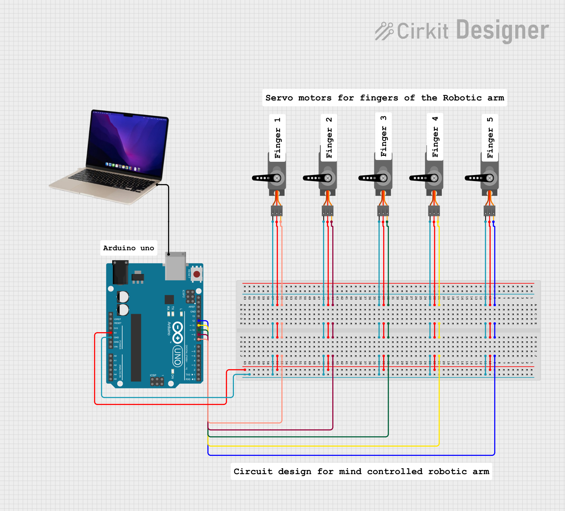 Open Project in Cirkit Designer
Explore Projects Built with Servo
Open Project in Cirkit DesignerOpen Project in Cirkit DesignerOpen Project in Cirkit DesignerOpen Project in Cirkit DesignerTechnical Specifications
Below are the general technical specifications for a standard hobby servo. Note that specifications may vary depending on the specific model and manufacturer.
Key Technical Details
- Operating Voltage: 4.8V to 6V (typical range)
- Operating Current: 100mA to 1A (depending on load)
- Torque: 1.5 kg-cm to 20 kg-cm (varies by model)
- Speed: 0.1 to 0.2 seconds per 60° (at no load)
- Control Signal: Pulse Width Modulation (PWM)
- Angle Range: 0° to 180° (standard), some models support 360° continuous rotation
- Connector Type: 3-pin (Signal, VCC, GND)
Pin Configuration and Descriptions
The servo typically has a 3-pin connector with the following pinout:
| Pin Number | Name | Description |
|---|---|---|
| 1 | Signal | Receives PWM signal for position control |
| 2 | VCC | Power supply (4.8V to 6V) |
| 3 | GND | Ground connection |
Usage Instructions
How to Use the Servo in a Circuit
- Power the Servo: Connect the VCC pin to a 5V or 6V power source and the GND pin to the ground of your circuit.
- Control Signal: Connect the Signal pin to a PWM-capable pin on your microcontroller (e.g., Arduino).
- PWM Signal: Send a PWM signal to the servo to control its position. The pulse width determines the angle:
- A pulse width of 1ms corresponds to 0°.
- A pulse width of 1.5ms corresponds to 90° (center position).
- A pulse width of 2ms corresponds to 180°.
Important Considerations and Best Practices
- Power Supply: Use a separate power supply for the servo if it draws significant current, as this can prevent voltage drops in your circuit.
- Avoid Overloading: Do not exceed the torque rating of the servo to avoid damage.
- PWM Frequency: Most servos operate at a PWM frequency of 50Hz (20ms period).
- Calibration: Some servos may require calibration to ensure accurate positioning.
Example: Connecting a Servo to an Arduino UNO
Below is an example of how to control a servo using an Arduino UNO:
#include <Servo.h> // Include the Servo library

Servo myServo; // Create a Servo object

void setup() {
  myServo.attach(9); // Attach the servo to pin 9 on the Arduino
}

void loop() {
  myServo.write(0); // Move the servo to 0 degrees
  delay(1000);      // Wait for 1 second

  myServo.write(90); // Move the servo to 90 degrees
  delay(1000);       // Wait for 1 second

  myServo.write(180); // Move the servo to 180 degrees
  delay(1000);        // Wait for 1 second
}
Explanation:
- The
Servolibrary simplifies controlling the servo. - The
attach()function links the servo to a specific pin. - The
write()function sets the servo angle (0° to 180°).
Troubleshooting and FAQs
Common Issues and Solutions
Servo Not Moving:
- Cause: Incorrect wiring or insufficient power supply.
- Solution: Double-check the connections and ensure the power supply meets the servo's requirements.
Servo Jittering:
- Cause: Electrical noise or unstable power supply.
- Solution: Use a capacitor across the power pins to stabilize the voltage.
Servo Overheating:
- Cause: Excessive load or continuous operation at high torque.
- Solution: Reduce the load or allow the servo to rest periodically.
Servo Not Reaching Full Range:
- Cause: Incorrect PWM signal or servo limitations.
- Solution: Verify the PWM signal timing and check the servo's specifications.
FAQs
Q: Can I connect multiple servos to an Arduino?
- A: Yes, but ensure the power supply can handle the combined current draw of all servos.
Q: What happens if I send a PWM signal outside the 1ms to 2ms range?
- A: The servo may behave unpredictably or attempt to move beyond its physical limits, potentially causing damage.
Q: Can I use a servo for continuous rotation?
- A: Yes, but you need a continuous rotation servo, which interprets PWM signals as speed and direction rather than position.
By following this documentation, you can effectively integrate and troubleshoot a servo in your projects.