How to Use ESP32-C3 PRO MINI: Examples, Pinouts, and Specs
Introduction
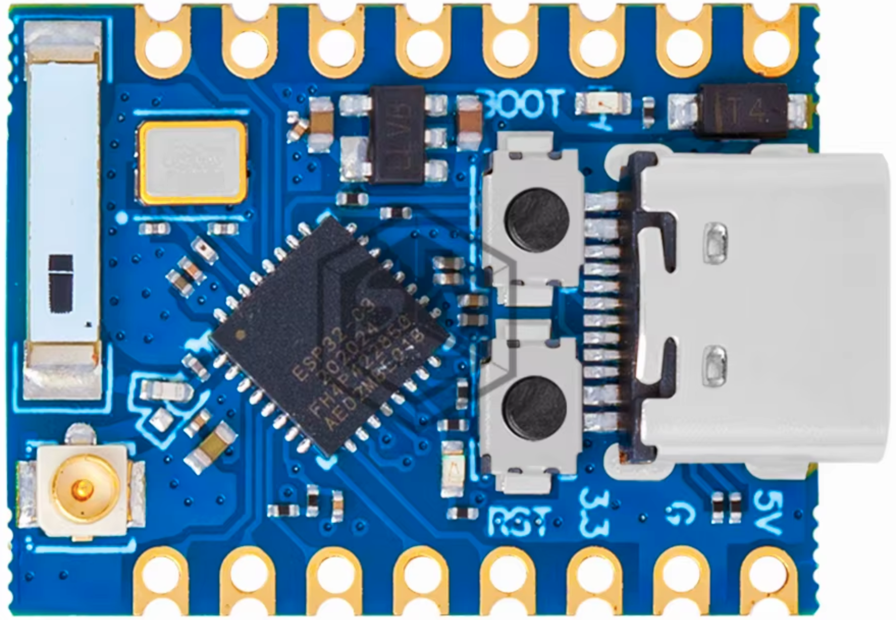
The ESP32-C3 PRO MINI is a compact and powerful microcontroller board designed for IoT applications and embedded systems. It is based on the ESP32-C3 chip, which features a RISC-V single-core processor, integrated Wi-Fi, and Bluetooth Low Energy (BLE) connectivity. This board is ideal for projects requiring wireless communication, low power consumption, and a small form factor.
Explore Projects Built with ESP32-C3 PRO MINI


Explore Projects Built with ESP32-C3 PRO MINI
Common Applications and Use Cases
- IoT devices and smart home automation
- Wearable technology
- Wireless sensor networks
- Remote monitoring and control systems
- Prototyping for Bluetooth and Wi-Fi-enabled devices
Technical Specifications
The following table outlines the key technical specifications of the ESP32-C3 PRO MINI:
| Specification | Details |
|---|---|
| Microcontroller | ESP32-C3 (RISC-V single-core processor, up to 160 MHz) |
| Flash Memory | 4 MB (external SPI flash) |
| SRAM | 400 KB |
| Wireless Connectivity | Wi-Fi 802.11 b/g/n (2.4 GHz), Bluetooth 5.0 LE |
| Operating Voltage | 3.3V |
| Input Voltage Range | 5V (via USB-C) or 3.3V (via pin headers) |
| GPIO Pins | 15 (multipurpose, including ADC, PWM, I2C, SPI, UART) |
| ADC Resolution | 12-bit |
| Interfaces | UART, SPI, I2C, I2S, PWM, ADC |
| Power Consumption | Ultra-low power modes supported |
| Dimensions | 18 mm x 25 mm |
Pin Configuration and Descriptions
The ESP32-C3 PRO MINI features a compact pinout. Below is the pin configuration:
| Pin | Name | Description |
|---|---|---|
| 1 | GND | Ground |
| 2 | 3V3 | 3.3V power output |
| 3 | EN | Enable pin (active high, used to reset the board) |
| 4 | GPIO0 | General-purpose I/O, boot mode selection |
| 5 | GPIO1 | General-purpose I/O, UART TXD |
| 6 | GPIO2 | General-purpose I/O, UART RXD |
| 7 | GPIO3 | General-purpose I/O, ADC input, PWM output |
| 8 | GPIO4 | General-purpose I/O, ADC input, PWM output |
| 9 | GPIO5 | General-purpose I/O, SPI SCK |
| 10 | GPIO6 | General-purpose I/O, SPI MISO |
| 11 | GPIO7 | General-purpose I/O, SPI MOSI |
| 12 | GPIO8 | General-purpose I/O, I2C SDA |
| 13 | GPIO9 | General-purpose I/O, I2C SCL |
| 14 | USB-C | USB-C connector for power and programming |
| 15 | RST | Reset pin (active low) |
Usage Instructions
How to Use the ESP32-C3 PRO MINI in a Circuit
- Powering the Board:
- Use a USB-C cable to supply 5V power to the board.
- Alternatively, provide 3.3V directly to the 3V3 pin. Ensure the voltage is regulated.
- Programming the Board:
- Connect the board to your computer via USB-C.
- Use the Arduino IDE or ESP-IDF (Espressif IoT Development Framework) for programming.
- Select "ESP32-C3 Dev Module" as the board in the Arduino IDE.
- Connecting Peripherals:
- Use the GPIO pins for interfacing with sensors, actuators, or other devices.
- Ensure the peripherals operate at 3.3V logic levels to avoid damaging the board.
Important Considerations and Best Practices
- Voltage Levels: The GPIO pins are not 5V tolerant. Always use level shifters if interfacing with 5V devices.
- Boot Mode: To enter bootloader mode, hold the GPIO0 pin low while resetting the board.
- Power Consumption: Use deep sleep modes to minimize power consumption in battery-powered applications.
- Antenna Placement: Ensure the onboard antenna has sufficient clearance from metal objects to avoid interference.
Example Code for Arduino UNO Integration
Below is an example of using the ESP32-C3 PRO MINI to read a temperature sensor and send data via Wi-Fi:
#include <WiFi.h>

// Replace with your network credentials
const char* ssid = "Your_SSID";
const char* password = "Your_PASSWORD";

void setup() {
  Serial.begin(115200); // Initialize serial communication
  WiFi.begin(ssid, password); // Connect to Wi-Fi

  // Wait for connection
  while (WiFi.status() != WL_CONNECTED) {
    delay(1000);
    Serial.println("Connecting to Wi-Fi...");
  }
  Serial.println("Connected to Wi-Fi");
}

void loop() {
  // Example: Simulate reading temperature data
  float temperature = 25.0 + random(-5, 5) * 0.1; // Simulated temperature value
  Serial.print("Temperature: ");
  Serial.print(temperature);
  Serial.println(" °C");

  delay(2000); // Wait 2 seconds before the next reading
}
Troubleshooting and FAQs
Common Issues and Solutions
Board Not Detected by Computer:
- Ensure the USB-C cable supports data transfer (not just charging).
- Install the necessary USB-to-serial drivers for the ESP32-C3.
Wi-Fi Connection Fails:
- Double-check the SSID and password in your code.
- Ensure the Wi-Fi network operates on the 2.4 GHz band (not 5 GHz).
GPIO Pin Not Responding:
- Verify the pin mode is correctly set in your code (e.g.,
pinMode(pin, OUTPUT)). - Check for short circuits or incorrect wiring.
- Verify the pin mode is correctly set in your code (e.g.,
High Power Consumption:
- Use deep sleep modes when the board is idle.
- Disconnect unused peripherals to reduce power draw.
FAQs
Q: Can I use the ESP32-C3 PRO MINI with a 5V sensor?
A: No, the GPIO pins are not 5V tolerant. Use a level shifter to interface with 5V sensors.
Q: How do I reset the board?
A: Press the RST pin or the reset button on the board.
Q: What is the maximum Wi-Fi range?
A: The range depends on environmental factors but typically extends up to 50 meters indoors and 200 meters outdoors.
Q: Can I use the ESP32-C3 PRO MINI with batteries?
A: Yes, you can power the board with a 3.7V LiPo battery and a voltage regulator to provide 3.3V.