Cirkit Designer Logo
Cirkit Designer
Your all-in-one circuit design IDE
Home / 
Component Documentation

How to Use TC7SU04F: Examples, Pinouts, and Specs
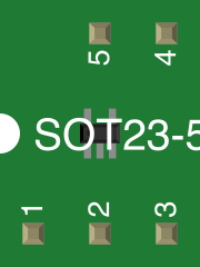

Image of TC7SU04F
Cirkit Designer LogoDesign with TC7SU04F in Cirkit Designer

Introduction

The TC7SU04F is a single hex inverter gate designed for use in digital circuits. It operates at low voltage and delivers high-speed performance, making it ideal for applications requiring efficient logic level inversion. This component is part of the TC7 series, which is renowned for its low power consumption and high noise immunity. The TC7SU04F is commonly used in signal processing, logic level conversion, and other digital logic applications.

Explore Projects Built with TC7SU04F

Use Cirkit Designer to design, explore, and prototype these projects online. Some projects support real-time simulation. Click "Open Project" to start designing instantly!
Battery-Powered Emergency Alert System with NUCLEO-F072RB, SIM800L, and GPS NEO 6M
Image of women safety: A project utilizing TC7SU04F in a practical application
This circuit is an emergency alert system that uses a NUCLEO-F072RB microcontroller to send SMS alerts and make calls via a SIM800L GSM module, while obtaining location data from a GPS NEO 6M module. The system is powered by a Li-ion battery and includes a TP4056 module for battery charging and protection, with a rocker switch to control power to the microcontroller.
Cirkit Designer LogoOpen Project in Cirkit Designer
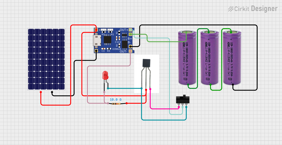
Solar-Powered LED Light with TP4056 Charging Module and Transistor Switch
Image of led: A project utilizing TC7SU04F in a practical application
This circuit appears to be a solar-powered charging system with a battery backup. The TP4056 is used for charging and power management, connected to a solar panel and two 3.3V batteries. A BC557 transistor, controlled by the solar panel voltage through a resistor, likely serves as a switch to enable charging from the solar panel when sufficient light is available, while the toggle switch allows manual control of the power flow to the LED.
Cirkit Designer LogoOpen Project in Cirkit Designer
Cellular-Enabled IoT Device with Real-Time Clock and Power Management
Image of LRCM PHASE 2 BASIC: A project utilizing TC7SU04F in a practical application
This circuit features a LilyGo-SIM7000G module for cellular communication and GPS functionality, interfaced with an RTC DS3231 for real-time clock capabilities. It includes voltage sensing through two voltage sensor modules, and uses an 8-channel opto-coupler for isolating different parts of the circuit. Power management is handled by a buck converter connected to a DC power source and batteries, with a fuse for protection and a rocker switch for on/off control. Additionally, there's an LED for indication purposes.
Cirkit Designer LogoOpen Project in Cirkit Designer
Satellite-Based Timing and Navigation System with SDR and Atomic Clock Synchronization
Image of GPS 시스템 측정 구성도_Confirm: A project utilizing TC7SU04F in a practical application
This circuit appears to be a complex system involving power supply management, GPS and timing synchronization, and data communication. It includes a SI-TEX G1 Satellite Compass for GPS data, an XHTF1021 Atomic Rubidium Clock for precise timing, and Ettus USRP B200 units for software-defined radio communication. Power is supplied through various SMPS units and distributed via terminal blocks and DC jacks. Data communication is facilitated by Beelink MINI S12 N95 computers, RS232 splitters, and a 1000BASE-T Media Converter for network connectivity. RF Directional Couplers are used to interface antennas with the USRP units, and the entire system is likely contained within cases for protection and organization.
Cirkit Designer LogoOpen Project in Cirkit Designer

Explore Projects Built with TC7SU04F

Use Cirkit Designer to design, explore, and prototype these projects online. Some projects support real-time simulation. Click "Open Project" to start designing instantly!
Image of women safety: A project utilizing TC7SU04F in a practical application
Battery-Powered Emergency Alert System with NUCLEO-F072RB, SIM800L, and GPS NEO 6M
This circuit is an emergency alert system that uses a NUCLEO-F072RB microcontroller to send SMS alerts and make calls via a SIM800L GSM module, while obtaining location data from a GPS NEO 6M module. The system is powered by a Li-ion battery and includes a TP4056 module for battery charging and protection, with a rocker switch to control power to the microcontroller.
Cirkit Designer LogoOpen Project in Cirkit Designer
Image of led: A project utilizing TC7SU04F in a practical application
Solar-Powered LED Light with TP4056 Charging Module and Transistor Switch
This circuit appears to be a solar-powered charging system with a battery backup. The TP4056 is used for charging and power management, connected to a solar panel and two 3.3V batteries. A BC557 transistor, controlled by the solar panel voltage through a resistor, likely serves as a switch to enable charging from the solar panel when sufficient light is available, while the toggle switch allows manual control of the power flow to the LED.
Cirkit Designer LogoOpen Project in Cirkit Designer
Image of LRCM PHASE 2 BASIC: A project utilizing TC7SU04F in a practical application
Cellular-Enabled IoT Device with Real-Time Clock and Power Management
This circuit features a LilyGo-SIM7000G module for cellular communication and GPS functionality, interfaced with an RTC DS3231 for real-time clock capabilities. It includes voltage sensing through two voltage sensor modules, and uses an 8-channel opto-coupler for isolating different parts of the circuit. Power management is handled by a buck converter connected to a DC power source and batteries, with a fuse for protection and a rocker switch for on/off control. Additionally, there's an LED for indication purposes.
Cirkit Designer LogoOpen Project in Cirkit Designer
Image of GPS 시스템 측정 구성도_Confirm: A project utilizing TC7SU04F in a practical application
Satellite-Based Timing and Navigation System with SDR and Atomic Clock Synchronization
This circuit appears to be a complex system involving power supply management, GPS and timing synchronization, and data communication. It includes a SI-TEX G1 Satellite Compass for GPS data, an XHTF1021 Atomic Rubidium Clock for precise timing, and Ettus USRP B200 units for software-defined radio communication. Power is supplied through various SMPS units and distributed via terminal blocks and DC jacks. Data communication is facilitated by Beelink MINI S12 N95 computers, RS232 splitters, and a 1000BASE-T Media Converter for network connectivity. RF Directional Couplers are used to interface antennas with the USRP units, and the entire system is likely contained within cases for protection and organization.
Cirkit Designer LogoOpen Project in Cirkit Designer

Common Applications:

  • Signal inversion in digital circuits
  • Logic level conversion
  • High-speed data processing
  • Low-power digital systems

Technical Specifications

Key Technical Details:

Parameter Value
Supply Voltage (Vcc) 2.0V to 5.5V
Input Voltage (Vin) 0V to 5.5V
Output Voltage (Vout) 0V to Vcc
High-Level Output Current (Ioh) -2.0mA (at Vcc = 3.3V)
Low-Level Output Current (Iol) 2.0mA (at Vcc = 3.3V)
Propagation Delay (tpd) 3.5ns (typical at Vcc = 5.0V)
Power Dissipation 200mW (maximum)
Operating Temperature -40°C to +85°C
Package Type SOT-353

Pin Configuration and Descriptions:

The TC7SU04F is a 5-pin device in a compact SOT-353 package. The pinout is as follows:

Pin Number Pin Name Description
1 A Input (logic signal to be inverted)
2 GND Ground (0V reference)
3 Y Output (inverted logic signal)
4 Vcc Supply Voltage
5 NC No Connection

Usage Instructions

How to Use the TC7SU04F in a Circuit:

  1. Power Supply: Connect the Vcc pin (Pin 4) to a stable power supply within the range of 2.0V to 5.5V. Connect the GND pin (Pin 2) to the ground of the circuit.
  2. Input Signal: Apply the logic signal to be inverted to the input pin (Pin 1, A). Ensure the input voltage does not exceed the specified range (0V to 5.5V).
  3. Output Signal: The inverted logic signal will be available at the output pin (Pin 3, Y). Connect this pin to the desired load or circuit.
  4. Bypass Capacitor: Place a decoupling capacitor (e.g., 0.1µF) between Vcc and GND to stabilize the power supply and reduce noise.

Important Considerations:

  • Avoid exceeding the absolute maximum ratings for voltage, current, and power dissipation to prevent damage to the component.
  • Ensure proper grounding to minimize noise and improve performance.
  • Use pull-up or pull-down resistors if required by the circuit design.

Example: Connecting TC7SU04F to an Arduino UNO

The TC7SU04F can be used with an Arduino UNO to invert a digital signal. Below is an example circuit and code:

Circuit:

  1. Connect the Vcc pin of the TC7SU04F to the 5V pin of the Arduino.
  2. Connect the GND pin of the TC7SU04F to the GND pin of the Arduino.
  3. Connect an Arduino digital output pin (e.g., D2) to the input pin (A) of the TC7SU04F.
  4. Connect the output pin (Y) of the TC7SU04F to an LED (with a current-limiting resistor) or another circuit.

Code:

// Arduino code to demonstrate signal inversion using TC7SU04F

const int inputPin = 2;  // Pin connected to TC7SU04F input (A)
const int outputPin = 3; // Pin connected to TC7SU04F output (Y)

void setup() {
  pinMode(inputPin, OUTPUT); // Set inputPin as output
  pinMode(outputPin, INPUT); // Set outputPin as input
}

void loop() {
  digitalWrite(inputPin, HIGH); // Send HIGH signal to TC7SU04F input
  delay(1000);                 // Wait for 1 second
  digitalWrite(inputPin, LOW);  // Send LOW signal to TC7SU04F input
  delay(1000);                 // Wait for 1 second
}

Troubleshooting and FAQs

Common Issues:

  1. No Output Signal:

    • Cause: Incorrect power supply or loose connections.
    • Solution: Verify that Vcc and GND are properly connected and the supply voltage is within the specified range.
  2. Output Signal Not Inverted:

    • Cause: Faulty input signal or damaged component.
    • Solution: Check the input signal with an oscilloscope or multimeter. Replace the component if necessary.
  3. Excessive Heat:

    • Cause: Exceeding maximum power dissipation or short circuit.
    • Solution: Ensure the load does not draw excessive current and check for short circuits.

FAQs:

Q1: Can the TC7SU04F operate at 3.3V?
A1: Yes, the TC7SU04F can operate at a supply voltage of 3.3V, which is within its specified range of 2.0V to 5.5V.

Q2: What is the maximum frequency the TC7SU04F can handle?
A2: The TC7SU04F has a typical propagation delay of 3.5ns at 5.0V, allowing it to handle frequencies up to approximately 140MHz.

Q3: Is the TC7SU04F suitable for analog signals?
A3: No, the TC7SU04F is designed for digital logic signals and may not perform well with analog signals.

Q4: Can I leave the NC pin unconnected?
A4: Yes, the NC (No Connection) pin does not need to be connected to any circuit.