How to Use LoRa_pcb: Examples, Pinouts, and Specs
Introduction
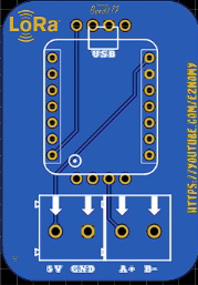
The LoRa_pcb is a printed circuit board designed specifically for LoRa (Long Range) communication. LoRa technology enables low-power, long-distance wireless data transmission, making it ideal for Internet of Things (IoT) applications. This component integrates the necessary circuitry to facilitate seamless communication between LoRa modules and other devices, such as microcontrollers or sensors.
Explore Projects Built with LoRa_pcb


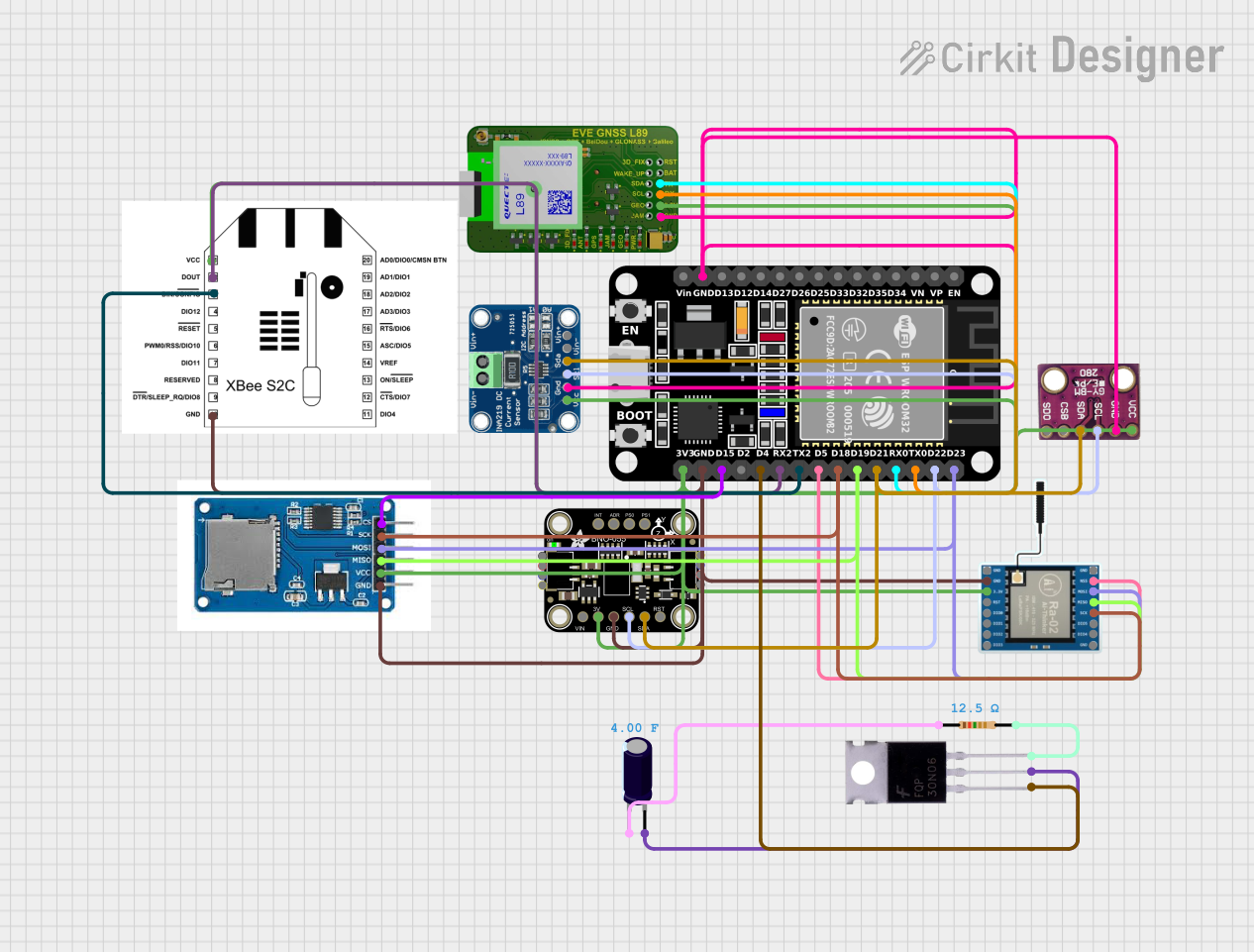
Explore Projects Built with LoRa_pcb
Common Applications and Use Cases
- Smart agriculture (e.g., soil moisture monitoring, weather stations)
- Industrial IoT (e.g., asset tracking, predictive maintenance)
- Smart cities (e.g., parking sensors, environmental monitoring)
- Home automation (e.g., smart meters, security systems)
- Remote monitoring and control systems
Technical Specifications
Key Technical Details
- Operating Voltage: 3.3V to 5V
- Communication Protocol: SPI (Serial Peripheral Interface)
- Frequency Bands: 433 MHz, 868 MHz, or 915 MHz (region-dependent)
- Power Consumption:
- Sleep mode: < 1 µA
- Transmit mode: ~120 mA (at maximum power)
- Range: Up to 15 km (line of sight, depending on environment)
- Data Rate: 0.3 kbps to 50 kbps
- Operating Temperature: -40°C to +85°C
- Dimensions: 25 mm x 35 mm (may vary by manufacturer)
Pin Configuration and Descriptions
The LoRa_pcb typically includes the following pins for interfacing:
| Pin Name | Type | Description |
|---|---|---|
| VCC | Power Input | Connect to a 3.3V or 5V power supply. |
| GND | Ground | Connect to the ground of the power supply. |
| MISO | SPI Output | Master In Slave Out - Data output from the LoRa module to the microcontroller. |
| MOSI | SPI Input | Master Out Slave In - Data input from the microcontroller to the LoRa module. |
| SCK | SPI Clock | Serial clock signal for SPI communication. |
| NSS | SPI Chip Select | Selects the LoRa module for communication. |
| DIO0 | Digital I/O | General-purpose digital I/O pin, often used for interrupt signaling. |
| RESET | Reset Input | Resets the LoRa module. |
| ANT | Antenna Output | Connect to an external antenna for wireless communication. |
Note: Pin configurations may vary slightly depending on the specific LoRa_pcb model. Always refer to the manufacturer's datasheet for exact details.
Usage Instructions
How to Use the LoRa_pcb in a Circuit
- Power Supply: Connect the VCC pin to a 3.3V or 5V power source and the GND pin to ground.
- SPI Communication: Connect the SPI pins (MISO, MOSI, SCK, NSS) to the corresponding pins on your microcontroller.
- Antenna: Attach an appropriate antenna to the ANT pin to ensure optimal signal transmission and reception.
- Interrupts: If required, connect the DIO0 pin to a digital input pin on your microcontroller for interrupt handling.
- Reset: Optionally, connect the RESET pin to a GPIO pin on your microcontroller for software-controlled resets.
Important Considerations and Best Practices
- Antenna Selection: Use an antenna that matches the frequency band of your LoRa module (e.g., 433 MHz, 868 MHz, or 915 MHz).
- Power Supply: Ensure a stable power supply to avoid communication issues.
- Environmental Factors: For maximum range, place the antenna in an open area with minimal obstructions.
- Regulatory Compliance: Verify that the frequency band used complies with local regulations.
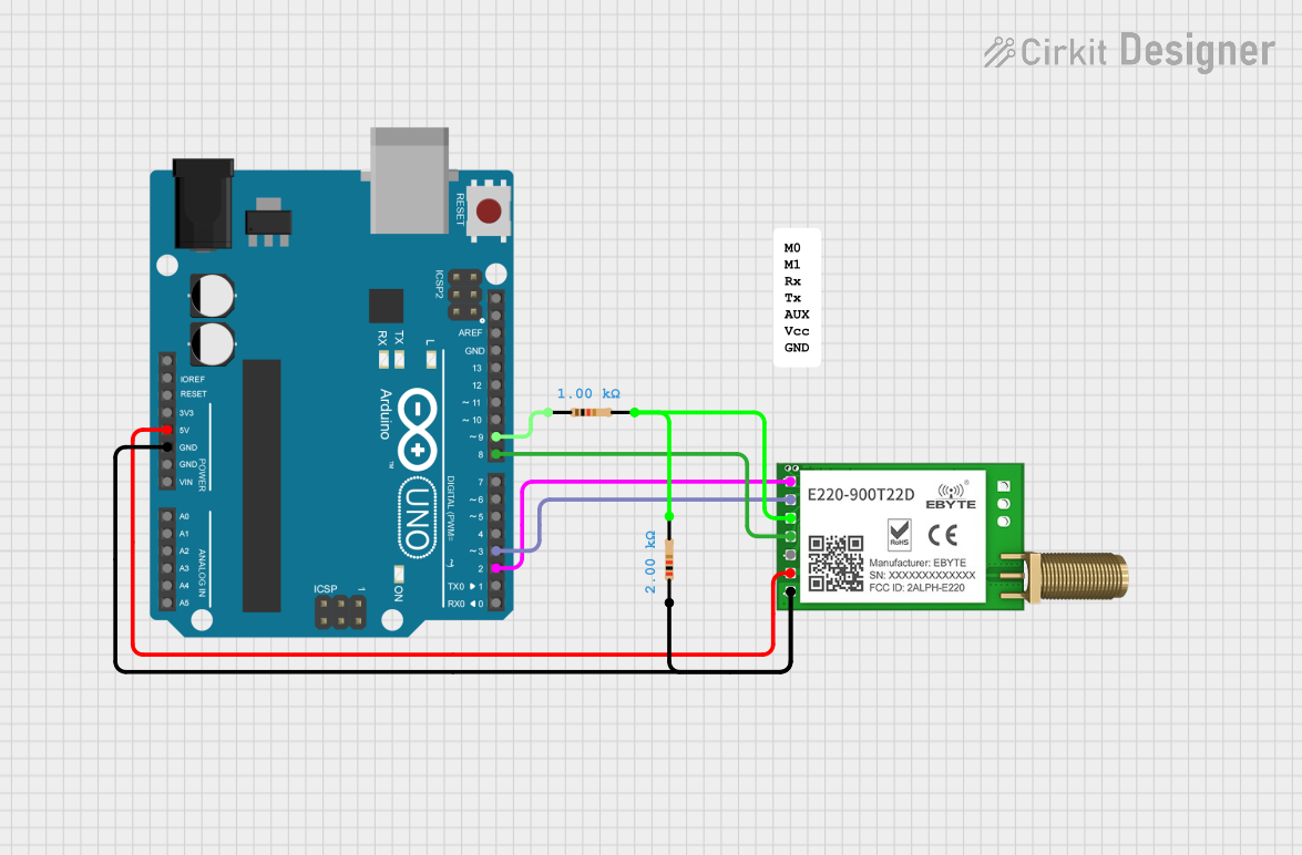
Example: Connecting LoRa_pcb to an Arduino UNO
Below is an example of how to connect and program the LoRa_pcb with an Arduino UNO using the popular LoRa library.
Wiring Diagram
| LoRa_pcb Pin | Arduino UNO Pin |
|---|---|
| VCC | 3.3V |
| GND | GND |
| MISO | Pin 12 |
| MOSI | Pin 11 |
| SCK | Pin 13 |
| NSS | Pin 10 |
| RESET | Pin 9 |
| DIO0 | Pin 2 |
Arduino Code Example
#include <SPI.h>
#include <LoRa.h>

// Define LoRa module pins
#define NSS 10
#define RESET 9
#define DIO0 2

void setup() {
  // Initialize serial communication for debugging
  Serial.begin(9600);
  while (!Serial);

  // Initialize LoRa module
  Serial.println("Initializing LoRa...");
  if (!LoRa.begin(915E6)) { // Set frequency to 915 MHz
    Serial.println("LoRa initialization failed!");
    while (1);
  }
  Serial.println("LoRa initialized successfully.");
}

void loop() {
  // Send a test message
  Serial.println("Sending packet...");
  LoRa.beginPacket();
  LoRa.print("Hello, LoRa!");
  LoRa.endPacket();

  // Wait for 5 seconds before sending the next packet
  delay(5000);
}
Note: Adjust the frequency in
LoRa.begin()to match your module's frequency band.
Troubleshooting and FAQs
Common Issues and Solutions
No Communication Between Devices
- Cause: Incorrect wiring or mismatched SPI pins.
- Solution: Double-check the connections and ensure the SPI pins are correctly mapped.
Short Range or Poor Signal Quality
- Cause: Improper antenna or environmental interference.
- Solution: Use a high-quality antenna and place it in an open area. Avoid obstacles like walls or metal objects.
LoRa Module Not Initializing
- Cause: Incorrect frequency or power supply issues.
- Solution: Verify the frequency in the code matches the module's frequency band. Ensure a stable power supply.
High Power Consumption
- Cause: Module stuck in transmit mode.
- Solution: Use sleep mode when the module is idle to reduce power consumption.
FAQs
Q: Can I use the LoRa_pcb with a 5V microcontroller?
A: Yes, the LoRa_pcb supports 5V logic levels, but always check the specific module's datasheet.Q: What is the maximum range of the LoRa_pcb?
A: The range can reach up to 15 km in line-of-sight conditions, but it depends on environmental factors and antenna quality.Q: How do I select the correct frequency band?
A: Choose the frequency band (433 MHz, 868 MHz, or 915 MHz) based on your region's regulations.Q: Can I connect multiple LoRa_pcb modules in a network?
A: Yes, LoRa supports point-to-point and star network topologies for multiple devices.
By following this documentation, you can effectively integrate the LoRa_pcb into your IoT projects and achieve reliable long-range communication.