How to Use RD03D: Examples, Pinouts, and Specs
Introduction
The RD03D is a high-frequency RF power transistor designed for use in various RF applications. It is widely recognized for its efficient amplification and reliable performance, making it an ideal choice for communication systems. This component is commonly used in RF amplifiers, transmitters, and other high-frequency circuits where stable and efficient signal amplification is required.
Explore Projects Built with RD03D


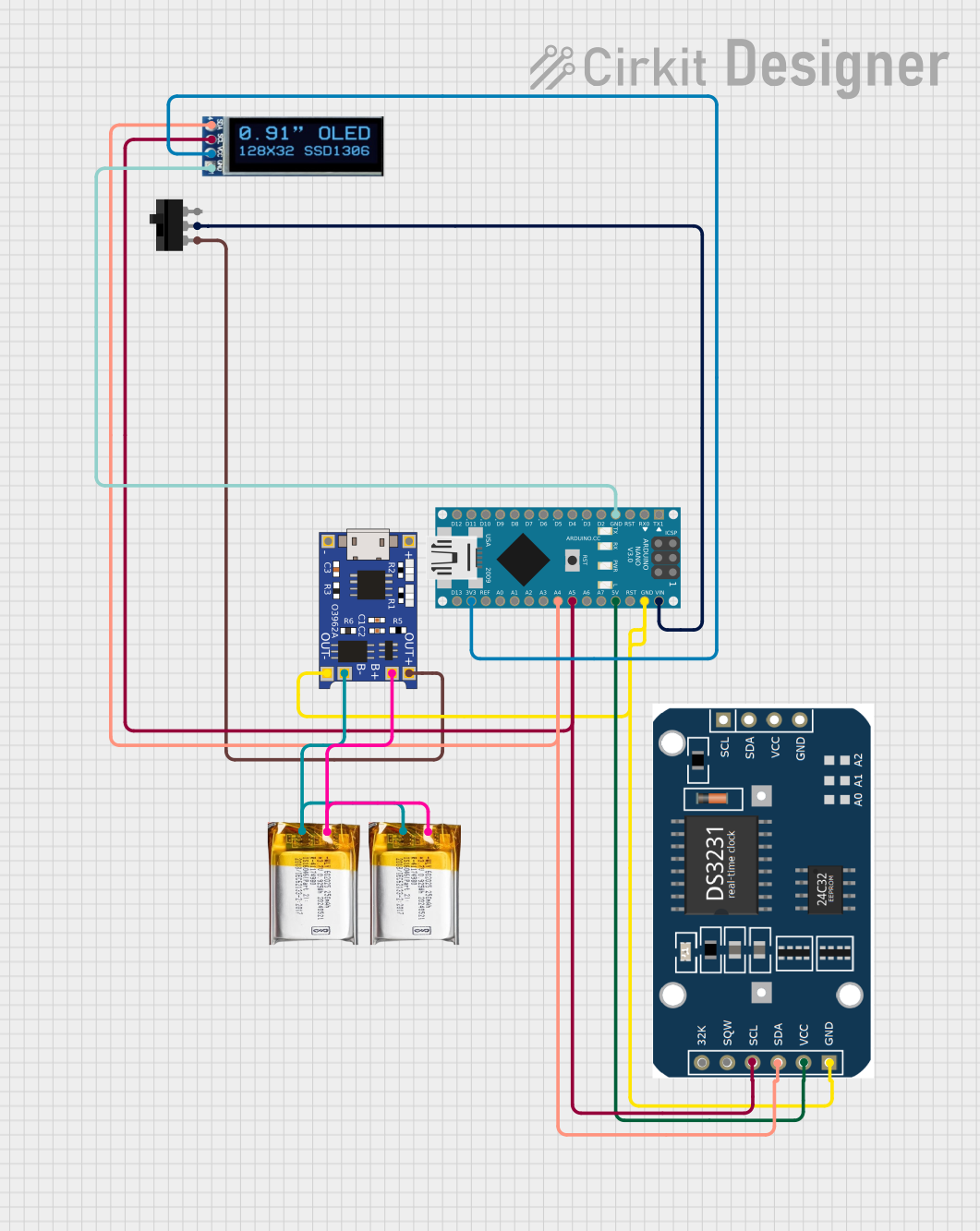
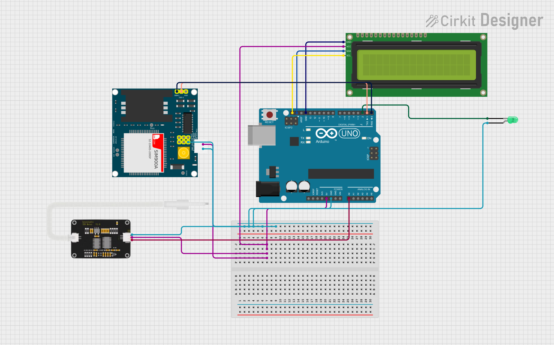
Explore Projects Built with RD03D
Common Applications and Use Cases
- RF amplifiers in communication systems
- Transmitters for amateur radio and commercial use
- Signal amplification in wireless communication devices
- Industrial RF equipment
Technical Specifications
The RD03D is designed to operate efficiently in high-frequency environments. Below are its key technical specifications:
| Parameter | Value |
|---|---|
| Frequency Range | Up to 1 GHz |
| Output Power | 3 Watts |
| Supply Voltage (Vcc) | 12.5 V |
| Input Power | 50 mW |
| Gain | 13 dB (typical) |
| Efficiency | 60% (typical) |
| Package Type | TO-220 |
| Operating Temperature | -30°C to +100°C |
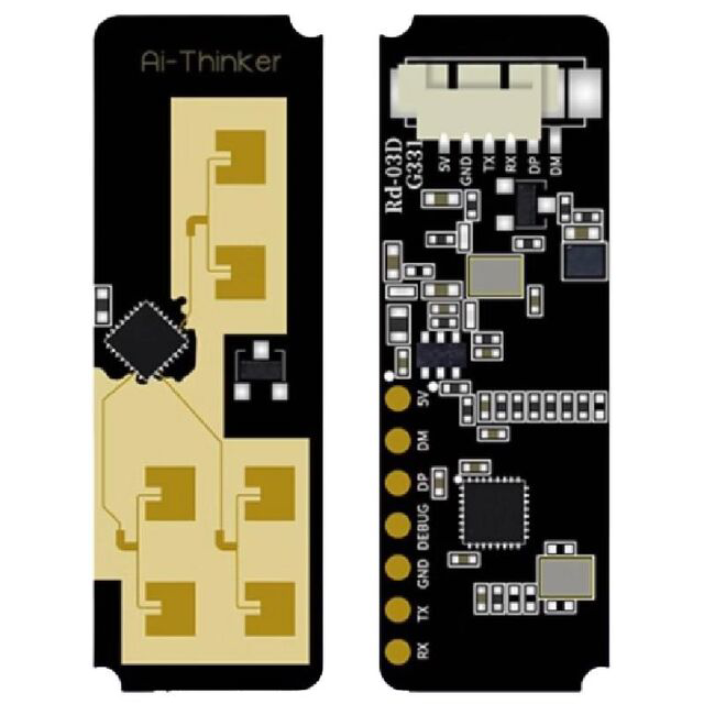
Pin Configuration and Descriptions
The RD03D is housed in a TO-220 package with three pins. The pin configuration is as follows:
| Pin Number | Pin Name | Description |
|---|---|---|
| 1 | Base | Input terminal for the RF signal |
| 2 | Collector | Output terminal for amplified RF signal |
| 3 | Emitter | Ground/reference terminal |
Usage Instructions
The RD03D is straightforward to use in RF circuits, but proper design considerations are essential to ensure optimal performance.
How to Use the RD03D in a Circuit
- Power Supply: Connect the collector (Pin 2) to a 12.5 V DC power supply. Ensure the power supply is stable and capable of delivering sufficient current.
- Input Signal: Feed the RF input signal to the base (Pin 1) through a coupling capacitor to block any DC component.
- Output Signal: The amplified RF signal can be extracted from the collector (Pin 2). Use a matching network to ensure impedance matching with the load.
- Grounding: Connect the emitter (Pin 3) to the ground plane of the circuit for proper operation.
Important Considerations and Best Practices
- Heat Dissipation: The RD03D can generate significant heat during operation. Use an appropriate heatsink to prevent overheating and ensure long-term reliability.
- Impedance Matching: Proper impedance matching is critical for maximizing power transfer and minimizing signal reflection.
- Bypass Capacitors: Use bypass capacitors near the power supply pin to filter out noise and stabilize the voltage.
- RF Shielding: To prevent interference, consider using RF shielding around the circuit.
Example: Using RD03D with an Arduino UNO
While the RD03D is not directly controlled by an Arduino, it can be used in conjunction with an Arduino to amplify RF signals generated by the microcontroller. Below is an example of how to use the RD03D in an RF circuit:
/*
  Example: Generating a PWM signal with Arduino UNO to drive the RD03D
  Note: This example demonstrates generating a signal. The RD03D will amplify
  this signal for RF applications. Ensure proper impedance matching and filtering.
*/

const int pwmPin = 9; // PWM output pin on Arduino UNO

void setup() {
  pinMode(pwmPin, OUTPUT); // Set the PWM pin as output
  // Configure Timer1 for a 1 kHz PWM signal
  analogWrite(pwmPin, 128); // Set 50% duty cycle (adjust as needed)
}

void loop() {
  // The RD03D will amplify the signal generated on pwmPin
  // Ensure the circuit is properly designed for RF amplification
}
Troubleshooting and FAQs
Common Issues and Solutions
No Output Signal
- Cause: Incorrect connections or insufficient input signal.
- Solution: Verify all connections, ensure the input signal is within the specified range, and check for proper power supply voltage.
Overheating
- Cause: Inadequate heat dissipation.
- Solution: Attach a heatsink to the RD03D and ensure proper ventilation.
Distorted Output Signal
- Cause: Impedance mismatch or insufficient bypassing.
- Solution: Use proper impedance matching networks and add bypass capacitors near the power supply.
Low Amplification
- Cause: Insufficient input power or degraded transistor.
- Solution: Check the input power level and replace the RD03D if necessary.
FAQs
Q1: Can the RD03D operate at frequencies above 1 GHz?
A1: No, the RD03D is designed for frequencies up to 1 GHz. Operating beyond this range may result in degraded performance.
Q2: What type of heatsink should I use?
A2: Use a TO-220-compatible heatsink with sufficient thermal dissipation capacity for the power levels in your application.
Q3: Can I use the RD03D for audio amplification?
A3: No, the RD03D is specifically designed for RF applications and is not suitable for audio frequency amplification.
Q4: How do I ensure proper impedance matching?
A4: Use an RF matching network (e.g., LC circuit) designed for the specific frequency and load impedance of your application.