How to Use ESP32 WROOM 38 PINS: Examples, Pinouts, and Specs
Introduction
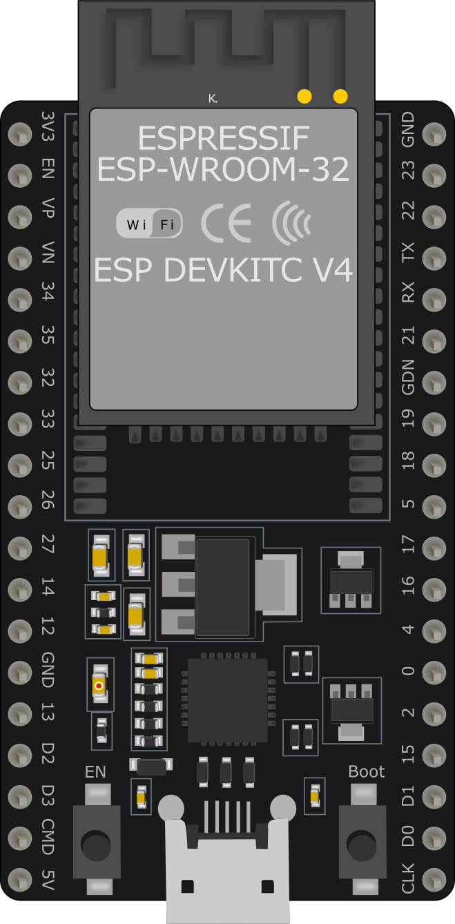
The ESP32 WROOM 38 PINS is a powerful microcontroller module designed for a wide range of applications, particularly in the Internet of Things (IoT) domain. It features integrated Wi-Fi and Bluetooth capabilities, making it ideal for wireless communication and smart device projects. With 38 GPIO pins, the ESP32 WROOM offers extensive interfacing options for sensors, actuators, and other peripherals.
Explore Projects Built with ESP32 WROOM 38 PINS


Explore Projects Built with ESP32 WROOM 38 PINS
Common Applications and Use Cases
- IoT devices and smart home automation
- Wireless sensor networks
- Wearable technology
- Robotics and automation systems
- Data logging and remote monitoring
- Prototyping and educational projects
Technical Specifications
The ESP32 WROOM 38 PINS module is built on the ESP32 chip, which combines high performance with low power consumption. Below are the key technical details:
| Specification | Details |
|---|---|
| Microcontroller | ESP32-D0WDQ6 |
| Wireless Connectivity | Wi-Fi 802.11 b/g/n, Bluetooth v4.2 + BLE |
| Operating Voltage | 3.3V |
| Input Voltage Range | 3.0V to 3.6V |
| Flash Memory | 4MB (default) |
| SRAM | 520KB |
| GPIO Pins | 38 |
| Clock Speed | Up to 240 MHz |
| Power Consumption | Ultra-low power consumption in deep sleep mode (as low as 10 µA) |
| Interfaces | UART, SPI, I2C, I2S, PWM, ADC, DAC |
| ADC Resolution | 12-bit |
| DAC Resolution | 8-bit |
| Operating Temperature | -40°C to 85°C |
| Dimensions | 25.5mm x 18mm |
Pin Configuration and Descriptions
The ESP32 WROOM 38 PINS module has 38 GPIO pins, each with specific functions. Below is a summary of the pin configuration:
| Pin Number | Pin Name | Function |
|---|---|---|
| 1 | EN | Enable pin (active high, used to reset the module) |
| 2 | IO0 | GPIO0, used for boot mode selection or general-purpose I/O |
| 3 | IO1 (TX0) | GPIO1, UART0 TX (default) |
| 4 | IO3 (RX0) | GPIO3, UART0 RX (default) |
| 5 | IO4 | GPIO4, general-purpose I/O |
| 6 | IO5 | GPIO5, general-purpose I/O |
| 7 | IO12 | GPIO12, supports ADC2 and touch functionality |
| 8 | IO13 | GPIO13, supports ADC2 and touch functionality |
| 9 | IO14 | GPIO14, supports ADC2 and touch functionality |
| 10 | IO15 | GPIO15, supports ADC2 and touch functionality |
| 11 | IO16 | GPIO16, general-purpose I/O |
| 12 | IO17 | GPIO17, general-purpose I/O |
| 13 | IO18 | GPIO18, supports SPI and PWM |
| 14 | IO19 | GPIO19, supports SPI and PWM |
| 15 | IO21 | GPIO21, supports I2C SDA |
| 16 | IO22 | GPIO22, supports I2C SCL |
| 17 | IO23 | GPIO23, supports SPI and PWM |
| 18 | IO25 | GPIO25, supports DAC1 and ADC2 |
| 19 | IO26 | GPIO26, supports DAC2 and ADC2 |
| 20 | IO27 | GPIO27, supports ADC2 |
| 21 | IO32 | GPIO32, supports ADC1 and touch functionality |
| 22 | IO33 | GPIO33, supports ADC1 and touch functionality |
| 23 | IO34 | GPIO34, input-only pin, supports ADC1 |
| 24 | IO35 | GPIO35, input-only pin, supports ADC1 |
| 25 | GND | Ground |
| 26 | 3V3 | 3.3V power supply |
Note: Some GPIO pins have dual or special functions. Refer to the ESP32 datasheet for detailed pin multiplexing information.
Usage Instructions
How to Use the ESP32 WROOM 38 PINS in a Circuit
Powering the Module:
- Provide a stable 3.3V power supply to the
3V3pin. Avoid exceeding the input voltage range (3.6V max). - Connect the
GNDpin to the ground of your circuit.
- Provide a stable 3.3V power supply to the
Programming the Module:
- Use a USB-to-Serial adapter to connect the ESP32 to your computer. Connect the
TXandRXpins of the adapter to theRX0andTX0pins of the ESP32, respectively. - Install the ESP32 board package in the Arduino IDE or use the ESP-IDF framework for advanced development.
- Use a USB-to-Serial adapter to connect the ESP32 to your computer. Connect the
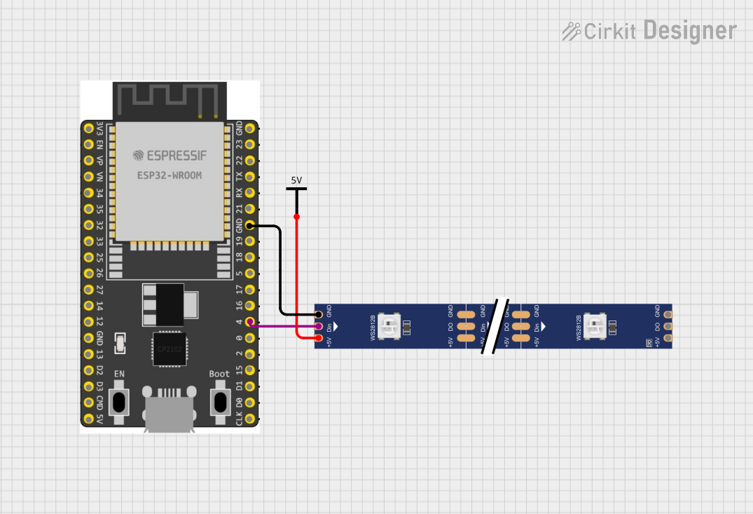
Connecting Peripherals:
- Use the GPIO pins to interface with sensors, actuators, and other devices. Ensure the voltage levels of connected peripherals are compatible with the ESP32's 3.3V logic.
Wi-Fi and Bluetooth Setup:
- Use the built-in libraries (e.g.,
WiFi.handBluetoothSerial.hin Arduino IDE) to configure wireless communication.
- Use the built-in libraries (e.g.,
Example: Blinking an LED with Arduino IDE
The following code demonstrates how to blink an LED connected to GPIO2:
// Define the GPIO pin for the LED
#define LED_PIN 2

void setup() {
  // Set the LED pin as an output
  pinMode(LED_PIN, OUTPUT);
}

void loop() {
  // Turn the LED on
  digitalWrite(LED_PIN, HIGH);
  delay(1000); // Wait for 1 second

  // Turn the LED off
  digitalWrite(LED_PIN, LOW);
  delay(1000); // Wait for 1 second
}
Important Considerations and Best Practices
- Voltage Levels: Ensure all connected peripherals operate at 3.3V logic levels. Use level shifters if necessary.
- Deep Sleep Mode: Use deep sleep mode to minimize power consumption in battery-powered applications.
- Boot Mode: GPIO0 must be pulled low during boot to enter programming mode.
- Avoid Floating Pins: Use pull-up or pull-down resistors to prevent floating GPIO pins.
Troubleshooting and FAQs
Common Issues and Solutions
ESP32 Not Detected by Computer:
- Ensure the USB-to-Serial adapter drivers are installed.
- Check the connections between the adapter and the ESP32.
Program Upload Fails:
- Verify that GPIO0 is pulled low during programming.
- Press the
EN(reset) button after initiating the upload.
Wi-Fi Connection Issues:
- Double-check the SSID and password in your code.
- Ensure the Wi-Fi network is within range and not using unsupported security protocols.
Random Resets or Instability:
- Use a stable power supply with sufficient current (at least 500mA).
- Add decoupling capacitors near the power pins.
FAQs
Q: Can I use 5V peripherals with the ESP32?
A: No, the ESP32 operates at 3.3V logic levels. Use level shifters to interface with 5V devices.
Q: How do I update the ESP32 firmware?
A: Use the ESP-IDF or Arduino IDE to upload new firmware. Ensure the correct board and port are selected.
Q: What is the maximum number of devices I can connect via Bluetooth?
A: The ESP32 supports up to 7 simultaneous Bluetooth connections in classic mode.
Q: Can I use the ESP32 for audio applications?
A: Yes, the ESP32 supports I2S for audio input/output and can be used in audio streaming or processing projects.