How to Use MAX30102 Heart Rate and Oxygen Sensor: Examples, Pinouts, and Specs
Introduction
The MAX30102 is an integrated pulse oximetry and heart-rate monitor sensor solution. It combines two LEDs, a photodetector, optimized optics, and low-noise analog signal processing to detect pulse oximetry and heart-rate signals. The MAX30102 is widely used in wearable devices, fitness accessories, and medical monitoring devices due to its high sensitivity, small form factor, and low power consumption.
Explore Projects Built with MAX30102 Heart Rate and Oxygen Sensor
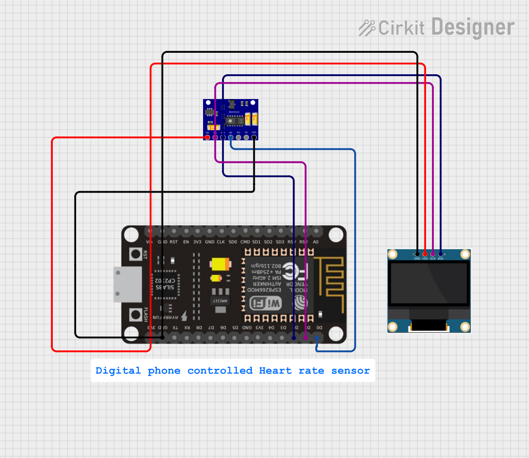
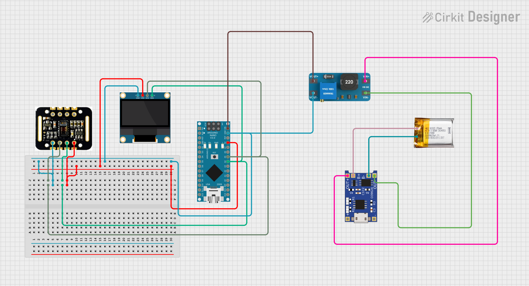
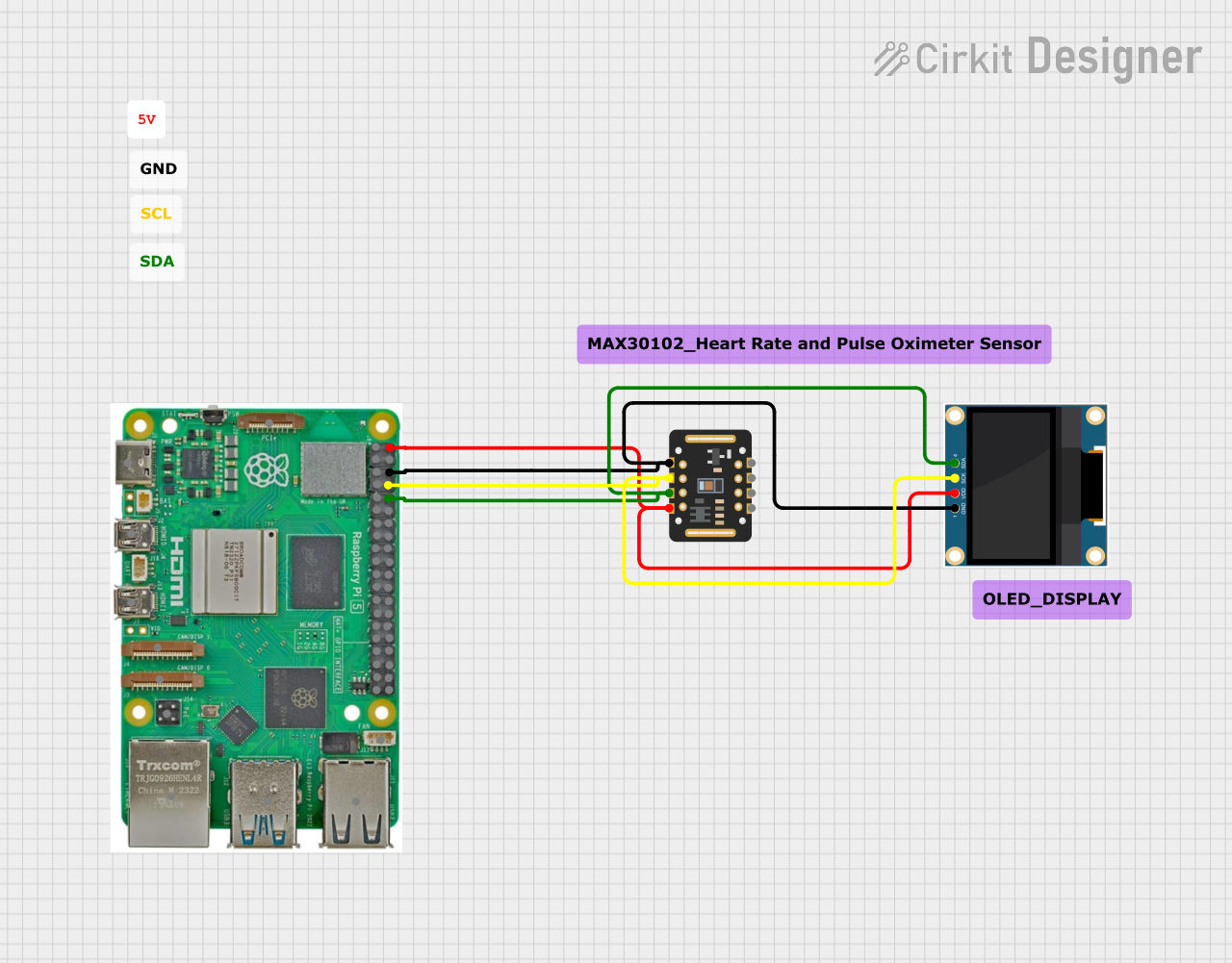
Explore Projects Built with MAX30102 Heart Rate and Oxygen Sensor
Common Applications and Use Cases
- Wearable devices such as fitness trackers and smartwatches
- Portable medical monitoring devices
- Sleep monitoring systems
- Remote patient monitoring
Technical Specifications
Key Technical Details
- Power Supply Voltage: 1.8V (core), 3.3V to 5V (I/O)
- Operating Current: 600µA (typical)
- Operating Temperature Range: -40°C to +85°C
- Communication Interface: I2C interface
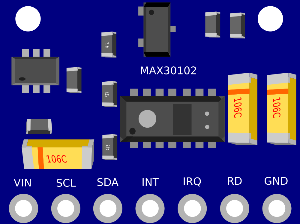
Pin Configuration and Descriptions
| Pin Number | Name | Description |
|---|---|---|
| 1 | VIN | Supply voltage for the sensor (3.3V to 5V) |
| 2 | SDA | I2C Data Line |
| 3 | SCL | I2C Clock Line |
| 4 | INT | Interrupt pin. Active low |
| 5 | IRD | Infrared LED cathode |
| 6 | RD | Red LED cathode |
| 7 | GND | Ground |
Usage Instructions
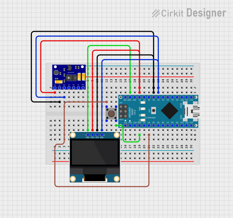
How to Use the Component in a Circuit
- Connect the VIN pin to a 3.3V to 5V power supply.
- Connect the GND pin to the ground of the power supply.
- Connect the SDA and SCL pins to the I2C data and clock lines, respectively.
- Optionally, connect the INT pin to an interrupt-capable GPIO pin on your microcontroller.
Important Considerations and Best Practices
- Ensure that the power supply is stable and within the specified voltage range.
- Use pull-up resistors on the I2C lines (SDA and SCL) if they are not provided on the breakout board.
- Avoid placing the sensor under direct sunlight or strong infrared sources to prevent inaccurate readings.
- Keep the sensor at a stable temperature to ensure accurate measurements.
Example Code for Arduino UNO
#include <Wire.h>
#include "MAX30105.h" // Use the appropriate library for MAX30102

MAX30105 particleSensor;

void setup() {
  Serial.begin(115200);
  if (!particleSensor.begin(Wire, I2C_SPEED_FAST)) { // Initialize sensor
    Serial.println("MAX30102 was not found. Please check wiring/power.");
    while (1);
  }
  particleSensor.setup(); // Configure sensor with default settings
  particleSensor.setPulseAmplitudeRed(0x0A); // Set Red LED amplitude
  particleSensor.setPulseAmplitudeIR(0x0A); // Set IR LED amplitude
}

void loop() {
  long irValue = particleSensor.getIR(); // Read IR value
  if (irValue > 50000) { // Check if the IR signal is strong enough
    Serial.print("Heart rate: ");
    Serial.print(particleSensor.getHeartRate()); // Get heart rate
    Serial.print(" bpm - SpO2: ");
    Serial.print(particleSensor.getSpO2()); // Get SpO2 value
    Serial.println("%");
  } else {
    Serial.println("No finger detected.");
  }
  delay(1000);
}
Troubleshooting and FAQs
Common Issues Users Might Face
- Inaccurate Readings: Ensure that the sensor is not exposed to external light sources and that it is in firm contact with the skin.
- No Data on Serial Monitor: Check the I2C connections and ensure that the correct I2C address is used in the code.
- Sensor Not Detected: Verify the power supply and connections. Ensure that the sensor is correctly soldered if using a breakout board.
Solutions and Tips for Troubleshooting
- Use a multimeter to check the voltage levels at VIN and GND.
- Ensure that the I2C pull-up resistors are correctly sized for your microcontroller's logic level.
- Check the solder joints on the breakout board for cold solder or short circuits.
FAQs
Q: Can the MAX30102 be used on a 5V system? A: Yes, the VIN pin can handle 3.3V to 5V, but the logic levels for I2C should be level-shifted if necessary.
Q: How can I improve the accuracy of the sensor? A: Ensure stable contact with the skin, avoid motion artifacts, and filter the signal in software if needed.
Q: What is the I2C address of the MAX30102? A: The default I2C address for the MAX30102 is 0x57 (7-bit address).
Q: Can the MAX30102 measure heart rate through clothes? A: No, the sensor needs to be in direct contact with the skin to measure heart rate and SpO2 accurately.