How to Use GT-24: Examples, Pinouts, and Specs
Introduction
The GT-24 is a general-purpose transistor designed for switching and amplification in electronic circuits. It is widely recognized for its reliability, efficiency, and versatility, making it a popular choice for hobbyists and professionals alike. The GT-24 can be used in a variety of applications, including signal amplification, motor control, and digital switching.
Explore Projects Built with GT-24

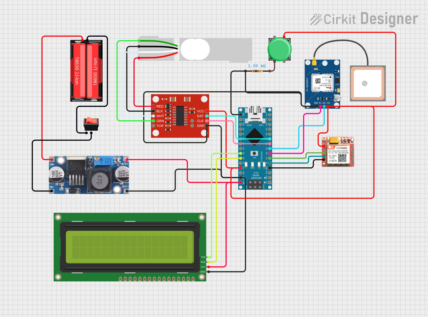


Explore Projects Built with GT-24
Common Applications:
- Signal amplification in audio and RF circuits
- Switching small loads in digital circuits
- Motor speed control and LED dimming
- General-purpose use in prototyping and educational projects
Technical Specifications
Below are the key technical details of the GT-24 transistor:
| Parameter | Value |
|---|---|
| Type | NPN Bipolar Junction Transistor (BJT) |
| Maximum Collector-Emitter Voltage (VCE) | 40V |
| Maximum Collector Current (IC) | 800mA |
| Maximum Power Dissipation (PD) | 500mW |
| DC Current Gain (hFE) | 100 - 300 |
| Transition Frequency (fT) | 150 MHz |
| Package Type | TO-92 |
Pin Configuration
The GT-24 transistor comes in a TO-92 package with three pins. The pinout is as follows:
| Pin Number | Pin Name | Description |
|---|---|---|
| 1 | Collector | Current flows into this pin during operation. |
| 2 | Base | Controls the transistor's operation. A small current here allows a larger current to flow between the collector and emitter. |
| 3 | Emitter | Current flows out of this pin. |
Usage Instructions
How to Use the GT-24 in a Circuit
- Determine the Configuration: Decide whether the GT-24 will be used in a common-emitter, common-base, or common-collector configuration based on your application.
- Connect the Pins:
- Connect the collector to the load or power supply.
- Connect the emitter to ground or the negative terminal of the power supply.
- Use a resistor to limit the base current and connect the base to the control signal.
- Calculate Resistor Values:
- Use Ohm's Law to calculate the base resistor value. Ensure the base current (IB) is sufficient to saturate the transistor when switching.
- For amplification, ensure the transistor operates in the active region by selecting appropriate resistor values.
- Power the Circuit: Apply the appropriate voltage to the circuit, ensuring it does not exceed the GT-24's maximum ratings.
Example: Using the GT-24 with an Arduino UNO
The following example demonstrates how to use the GT-24 to control an LED with an Arduino UNO.
Circuit Setup:
- Connect the collector of the GT-24 to one terminal of the LED.
- Connect the other terminal of the LED to a 220-ohm resistor, and then to the positive supply (5V).
- Connect the emitter of the GT-24 to ground.
- Connect the base of the GT-24 to a 1k-ohm resistor, and then to a digital pin on the Arduino (e.g., pin 9).
Arduino Code:
// Define the pin connected to the GT-24 base
const int transistorPin = 9;

void setup() {
  pinMode(transistorPin, OUTPUT); // Set the pin as an output
}

void loop() {
  digitalWrite(transistorPin, HIGH); // Turn on the LED
  delay(1000);                       // Wait for 1 second
  digitalWrite(transistorPin, LOW);  // Turn off the LED
  delay(1000);                       // Wait for 1 second
}
Important Considerations:
- Base Resistor: Always use a base resistor to limit the current and protect the transistor.
- Heat Dissipation: If the transistor operates near its maximum power dissipation, consider adding a heatsink.
- Voltage and Current Ratings: Ensure the voltage and current in your circuit do not exceed the GT-24's maximum ratings.
Troubleshooting and FAQs
Common Issues:
Transistor Not Switching:
- Cause: Insufficient base current.
- Solution: Check the base resistor value and ensure the base current is adequate.
Overheating:
- Cause: Exceeding the maximum power dissipation.
- Solution: Reduce the load current or add a heatsink.
No Output Signal:
- Cause: Incorrect pin connections.
- Solution: Verify the pinout and ensure proper connections.
LED Not Turning Off Completely:
- Cause: Leakage current through the transistor.
- Solution: Use a pull-down resistor on the base to ensure it is fully turned off.
FAQs:
Q: Can the GT-24 handle AC signals?
- A: Yes, the GT-24 can amplify AC signals when used in the active region.
Q: What is the maximum switching speed of the GT-24?
- A: The GT-24 has a transition frequency (fT) of 150 MHz, making it suitable for high-speed switching applications.
Q: Can I use the GT-24 without a base resistor?
- A: No, a base resistor is essential to limit the base current and prevent damage to the transistor.
By following this documentation, you can effectively use the GT-24 transistor in your electronic projects.