How to Use Photon2: Examples, Pinouts, and Specs
Introduction
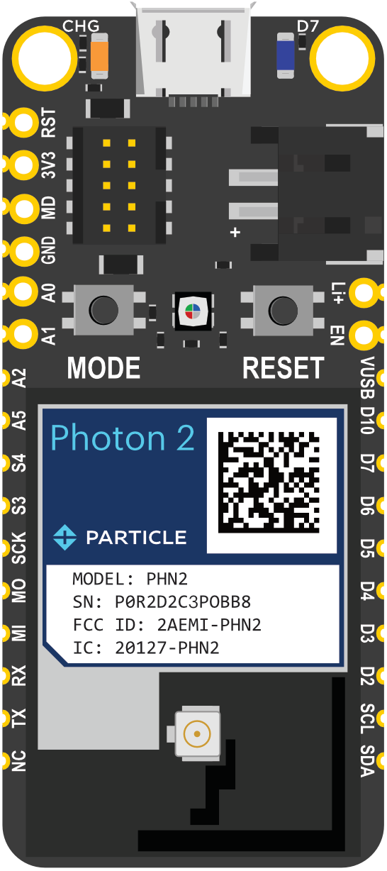
The Photon2 is a small, powerful Wi-Fi development kit designed for creating connected projects and products. It features a microcontroller with built-in Wi-Fi, making it ideal for Internet of Things (IoT) applications. The Photon2 is perfect for developers looking to build smart devices, home automation systems, and other connected solutions.
Explore Projects Built with Photon2
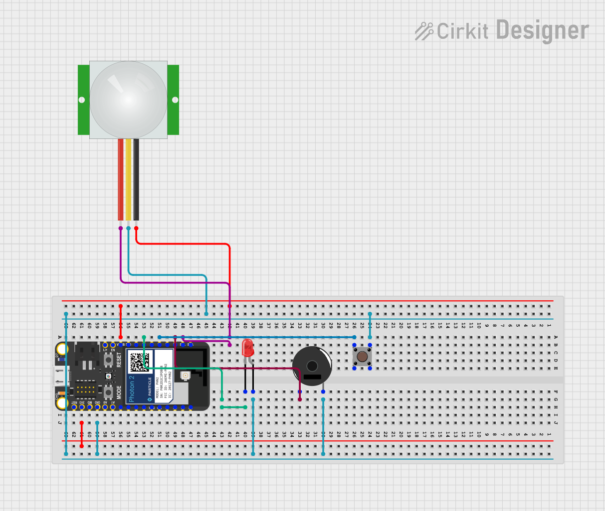
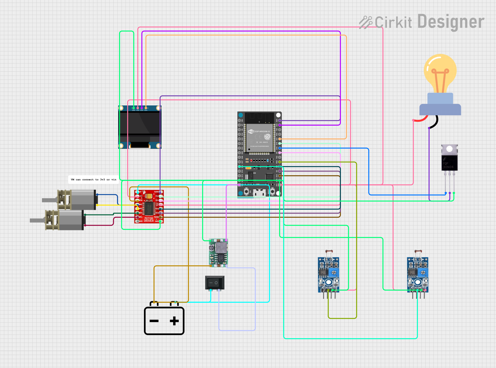
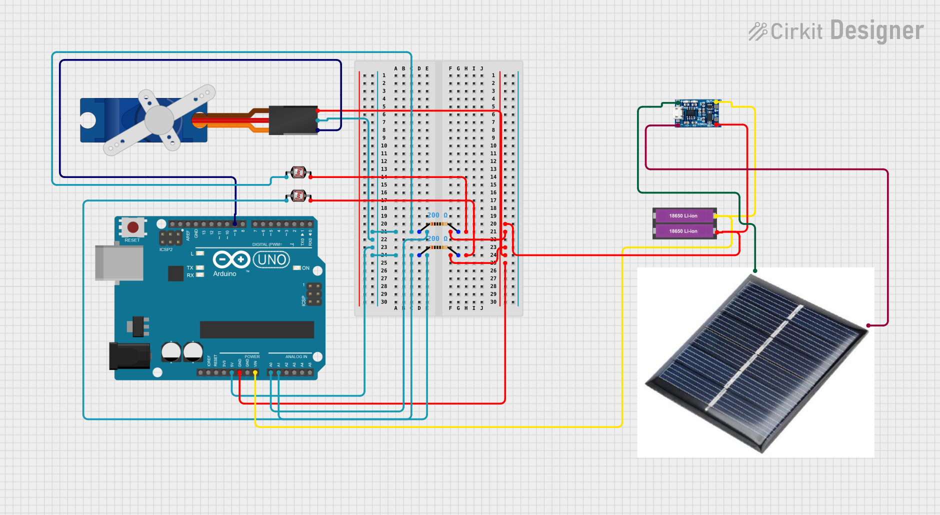
Explore Projects Built with Photon2
Technical Specifications
Key Technical Details
| Specification | Value |
|---|---|
| Microcontroller | ARM Cortex-M4 |
| Operating Voltage | 3.3V |
| Input Voltage | 3.6V - 5.5V |
| Digital I/O Pins | 18 |
| Analog Input Pins | 8 |
| Flash Memory | 1MB |
| SRAM | 256KB |
| Wi-Fi | 802.11 b/g/n |
| Clock Speed | 120 MHz |
| Dimensions | 36.58mm x 20.32mm |
Pin Configuration and Descriptions
| Pin Number | Pin Name | Description |
|---|---|---|
| 1 | VIN | Input voltage (3.6V - 5.5V) |
| 2 | GND | Ground |
| 3 | 3V3 | 3.3V output |
| 4 | D0 | Digital I/O |
| 5 | D1 | Digital I/O |
| 6 | D2 | Digital I/O |
| 7 | D3 | Digital I/O |
| 8 | D4 | Digital I/O |
| 9 | D5 | Digital I/O |
| 10 | D6 | Digital I/O |
| 11 | D7 | Digital I/O |
| 12 | A0 | Analog Input |
| 13 | A1 | Analog Input |
| 14 | A2 | Analog Input |
| 15 | A3 | Analog Input |
| 16 | A4 | Analog Input |
| 17 | A5 | Analog Input |
| 18 | A6 | Analog Input |
| 19 | A7 | Analog Input |
Usage Instructions
How to Use the Photon2 in a Circuit
Powering the Photon2:
- Connect the VIN pin to a power source (3.6V - 5.5V).
- Connect the GND pin to the ground of the power source.
Connecting to Wi-Fi:
- Use the built-in Wi-Fi module to connect to a Wi-Fi network.
- Configure the Wi-Fi settings using the provided libraries and functions.
Digital I/O:
- Use the digital I/O pins (D0 - D7) for interfacing with digital sensors, actuators, and other components.
- Configure the pins as input or output using the appropriate functions.
Analog Input:
- Use the analog input pins (A0 - A7) to read analog signals from sensors.
- Convert the analog signals to digital values using the built-in ADC.
Important Considerations and Best Practices
Power Supply:
- Ensure the input voltage is within the specified range (3.6V - 5.5V) to avoid damaging the Photon2.
- Use a stable power supply to prevent fluctuations that could affect performance.
Wi-Fi Configuration:
- Ensure the Wi-Fi credentials are correctly configured to establish a stable connection.
- Use secure Wi-Fi networks to protect your data and devices.
Pin Usage:
- Avoid exceeding the maximum current rating for the I/O pins to prevent damage.
- Use appropriate resistors and protection circuits when interfacing with external components.
Example Code
Here is an example of how to connect the Photon2 to an Arduino UNO and read an analog sensor value:
// Include necessary libraries
#include <Particle.h>

// Define the analog input pin
#define ANALOG_PIN A0

void setup() {
  // Initialize serial communication
  Serial.begin(9600);

  // Initialize the analog pin as input
  pinMode(ANALOG_PIN, INPUT);
}

void loop() {
  // Read the analog value from the sensor
  int sensorValue = analogRead(ANALOG_PIN);

  // Print the sensor value to the serial monitor
  Serial.println(sensorValue);

  // Wait for 1 second before reading again
  delay(1000);
}
Troubleshooting and FAQs
Common Issues
Wi-Fi Connection Problems:
- Solution: Ensure the Wi-Fi credentials are correct and the network is within range. Check for any interference or signal strength issues.
Power Supply Issues:
- Solution: Verify that the input voltage is within the specified range (3.6V - 5.5V). Use a stable power supply to avoid fluctuations.
Pin Configuration Errors:
- Solution: Double-check the pin configuration and ensure the pins are correctly set as input or output. Use appropriate resistors and protection circuits.
FAQs
Q1: Can I use the Photon2 with a 5V power supply?
- A1: Yes, the Photon2 can be powered with a voltage range of 3.6V to 5.5V.
Q2: How do I reset the Wi-Fi credentials on the Photon2?
- A2: You can reset the Wi-Fi credentials by holding down the SETUP button for 10 seconds until the LED starts blinking blue.
Q3: Can I use the Photon2 with other microcontrollers?
- A3: Yes, the Photon2 can be interfaced with other microcontrollers using the digital and analog I/O pins.
Q4: What is the maximum current rating for the I/O pins?
- A4: The maximum current rating for the I/O pins is 25mA per pin.
By following this documentation, you should be able to effectively use the Photon2 in your projects and troubleshoot common issues. Happy building!