Cirkit Designer Logo
Cirkit Designer
Your all-in-one circuit design IDE
Home / 
Component Documentation

How to Use 2 channel relay module: Examples, Pinouts, and Specs

Image of 2 channel relay module
Cirkit Designer LogoDesign with 2 channel relay module in Cirkit Designer

Introduction

A 2-channel relay module is an electronic switch that allows a low voltage or current signal to control a much higher voltage and current circuit. This module contains two independent relays that can be used to control various devices like motors, lights, and other home appliances. It is commonly used in automation projects, home automation systems, and with microcontrollers such as the Arduino UNO.

Explore Projects Built with 2 channel relay module

Use Cirkit Designer to design, explore, and prototype these projects online. Some projects support real-time simulation. Click "Open Project" to start designing instantly!
DC-DC Converter and Relay Module Power Distribution System
Image of relay: A project utilizing 2 channel relay module in a practical application
This circuit consists of a DC-DC converter powering a 6-channel power module, which in turn supplies 5V to a 2-relay module. The power module distributes the converted voltage to the relay module, enabling it to control external devices.
Cirkit Designer LogoOpen Project in Cirkit Designer
Arduino UNO Based Voltage Monitoring and Relay Control System
Image of power management : A project utilizing 2 channel relay module in a practical application
This circuit features an Arduino UNO connected to two voltage sensors and a 2-channel relay module. The Arduino monitors voltage levels through analog inputs A0 and A1, which are connected to the outputs of the voltage sensors. It controls the relay module via digital outputs D13 and D12, which are connected to the relay inputs IN1 and IN2, respectively, allowing the Arduino to switch external circuits on and off based on the voltage sensor readings.
Cirkit Designer LogoOpen Project in Cirkit Designer
ESP32 Wi-Fi Controlled Dual Relay Module
Image of esp: A project utilizing 2 channel relay module in a practical application
This circuit features an ESP32 microcontroller connected to a two-channel 5V relay module. The ESP32 controls the relay channels via its GPIO pins D23 and D22, allowing it to switch external devices on and off. The relay module is powered by the 3.3V and GND pins of the ESP32.
Cirkit Designer LogoOpen Project in Cirkit Designer
ESP32-Controlled Dual Relay Module
Image of ESP32 bluethooth with relay: A project utilizing 2 channel relay module in a practical application
This circuit features an ESP32 microcontroller connected to a two-channel relay module. The ESP32's digital pins D25 and D26 are used to control the relay channels IN1 and IN2, respectively, allowing the microcontroller to switch external circuits on and off. The ESP32 and the relay module share a common ground and the ESP32's Vin pin supplies power to the relay's VCC, indicating that both operate at compatible voltage levels.
Cirkit Designer LogoOpen Project in Cirkit Designer

Explore Projects Built with 2 channel relay module

Use Cirkit Designer to design, explore, and prototype these projects online. Some projects support real-time simulation. Click "Open Project" to start designing instantly!
Image of relay: A project utilizing 2 channel relay module in a practical application
DC-DC Converter and Relay Module Power Distribution System
This circuit consists of a DC-DC converter powering a 6-channel power module, which in turn supplies 5V to a 2-relay module. The power module distributes the converted voltage to the relay module, enabling it to control external devices.
Cirkit Designer LogoOpen Project in Cirkit Designer
Image of power management : A project utilizing 2 channel relay module in a practical application
Arduino UNO Based Voltage Monitoring and Relay Control System
This circuit features an Arduino UNO connected to two voltage sensors and a 2-channel relay module. The Arduino monitors voltage levels through analog inputs A0 and A1, which are connected to the outputs of the voltage sensors. It controls the relay module via digital outputs D13 and D12, which are connected to the relay inputs IN1 and IN2, respectively, allowing the Arduino to switch external circuits on and off based on the voltage sensor readings.
Cirkit Designer LogoOpen Project in Cirkit Designer
Image of esp: A project utilizing 2 channel relay module in a practical application
ESP32 Wi-Fi Controlled Dual Relay Module
This circuit features an ESP32 microcontroller connected to a two-channel 5V relay module. The ESP32 controls the relay channels via its GPIO pins D23 and D22, allowing it to switch external devices on and off. The relay module is powered by the 3.3V and GND pins of the ESP32.
Cirkit Designer LogoOpen Project in Cirkit Designer
Image of ESP32 bluethooth with relay: A project utilizing 2 channel relay module in a practical application
ESP32-Controlled Dual Relay Module
This circuit features an ESP32 microcontroller connected to a two-channel relay module. The ESP32's digital pins D25 and D26 are used to control the relay channels IN1 and IN2, respectively, allowing the microcontroller to switch external circuits on and off. The ESP32 and the relay module share a common ground and the ESP32's Vin pin supplies power to the relay's VCC, indicating that both operate at compatible voltage levels.
Cirkit Designer LogoOpen Project in Cirkit Designer

Technical Specifications

Key Technical Details

  • Operating Voltage (VCC): 5V DC
  • Trigger Voltage (IN1, IN2): 0-1.5V (LOW trigger), 2.5-5V (HIGH trigger)
  • Current Consumption: 15-20mA for one relay
  • Maximum Switching Voltage: 250VAC / 30VDC
  • Maximum Switching Current: 10A
  • Relay Life: 100,000 cycles (typical)

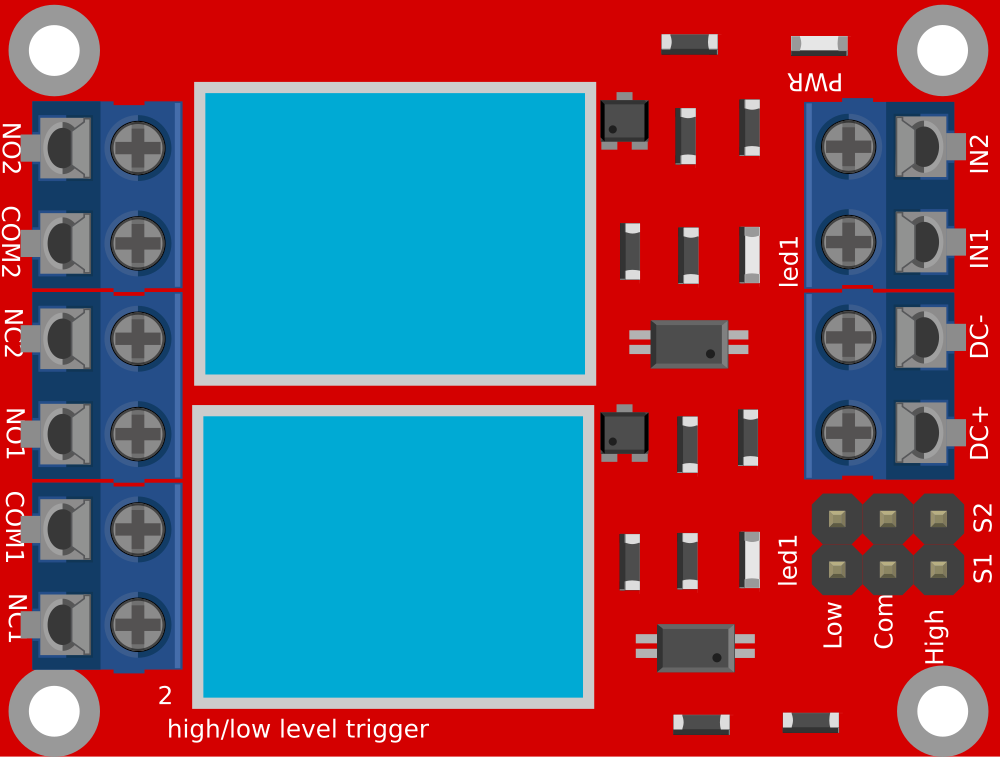
Pin Configuration and Descriptions

Pin Description
VCC Connect to 5V power supply
GND Connect to ground
IN1 Control signal for relay 1 (active LOW or HIGH depending on the module)
IN2 Control signal for relay 2 (active LOW or HIGH depending on the module)
NO1 Normally open contact for relay 1
COM1 Common contact for relay 1
NC1 Normally closed contact for relay 1
NO2 Normally open contact for relay 2
COM2 Common contact for relay 2
NC2 Normally closed contact for relay 2

Usage Instructions

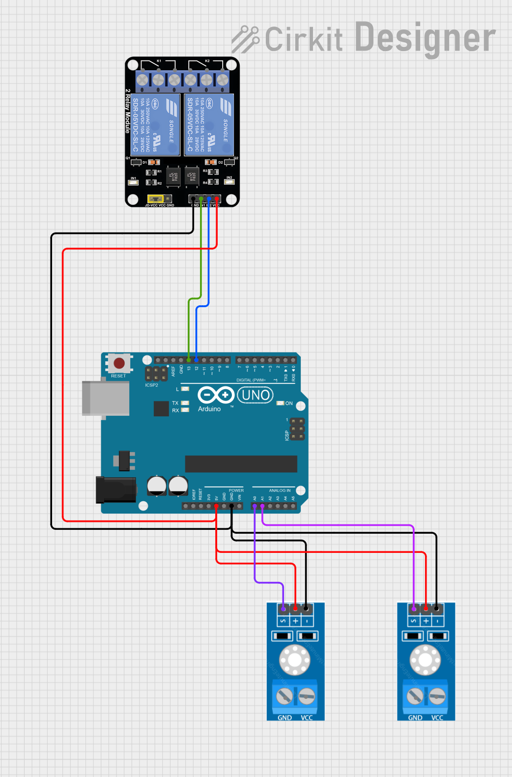
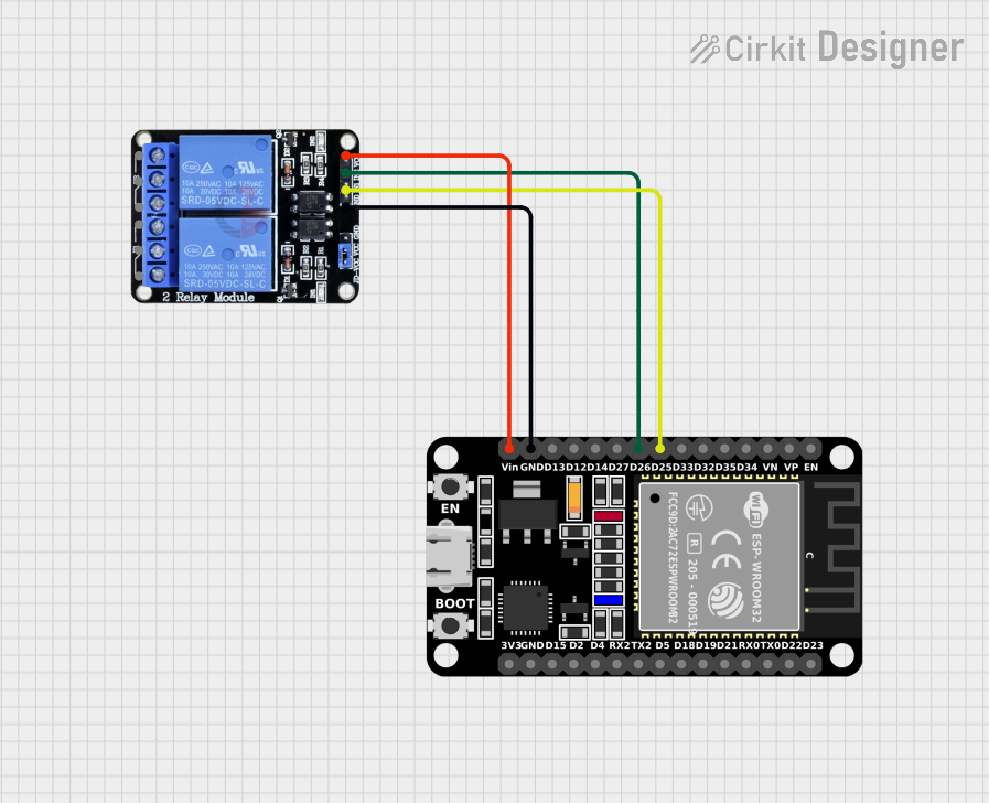
Connecting the Relay Module to a Circuit

  1. Connect the VCC pin to a 5V power supply.
  2. Connect the GND pin to the ground of the power supply.
  3. Connect the IN1 and IN2 pins to the digital outputs of a microcontroller.
  4. Connect the device you want to control to the NO (Normally Open) or NC (Normally Closed) and COM (Common) pins of the relay.

Important Considerations and Best Practices

  • Ensure that the power supply voltage matches the operating voltage of the relay module.
  • Do not exceed the maximum switching voltage and current ratings of the relays.
  • Use flyback diodes when controlling inductive loads to prevent back EMF damage.
  • Always ensure proper isolation when working with high voltage circuits.
  • Consider using a separate power supply for the relay coils to prevent noise in the microcontroller circuit.

Example Code for Arduino UNO

// Define relay control pins
const int relay1Pin = 2;
const int relay2Pin = 3;

void setup() {
  // Set relay pins as output
  pinMode(relay1Pin, OUTPUT);
  pinMode(relay2Pin, OUTPUT);
  
  // Initialize relays to OFF (assuming LOW trigger relays)
  digitalWrite(relay1Pin, HIGH);
  digitalWrite(relay2Pin, HIGH);
}

void loop() {
  // Turn on relay 1
  digitalWrite(relay1Pin, LOW);
  delay(1000); // Wait for 1 second
  
  // Turn off relay 1
  digitalWrite(relay1Pin, HIGH);
  delay(1000); // Wait for 1 second
  
  // Turn on relay 2
  digitalWrite(relay2Pin, LOW);
  delay(1000); // Wait for 1 second
  
  // Turn off relay 2
  digitalWrite(relay2Pin, HIGH);
  delay(1000); // Wait for 1 second
}

Troubleshooting and FAQs

Common Issues

  • Relay not activating: Check the input signal voltage and connections.
  • Intermittent operation: Verify that the power supply can deliver sufficient current.
  • Noise issues: Use a separate power supply for the relay module.

Solutions and Tips

  • If the relay does not switch, ensure that the control signal is within the correct voltage range.
  • For high-current applications, ensure that the relay contacts are not welding shut due to high inrush currents.
  • Use opto-isolation if there is a need to completely isolate the control circuitry from the high-power circuit.

FAQs

Q: Can I control the relay module with a 3.3V signal? A: Some relay modules can be triggered with 3.3V, but it's important to check the specifications of your specific module.

Q: Is it safe to switch AC loads with the relay module? A: Yes, but ensure that you are qualified to work with AC voltages and that all safety precautions are taken.

Q: Can I use PWM to control the relay module? A: No, relays require a steady LOW or HIGH signal to switch states. PWM signals will cause erratic behavior.