How to Use Adafruit Switched 12mm Coin Cell Breakout: Examples, Pinouts, and Specs
Introduction
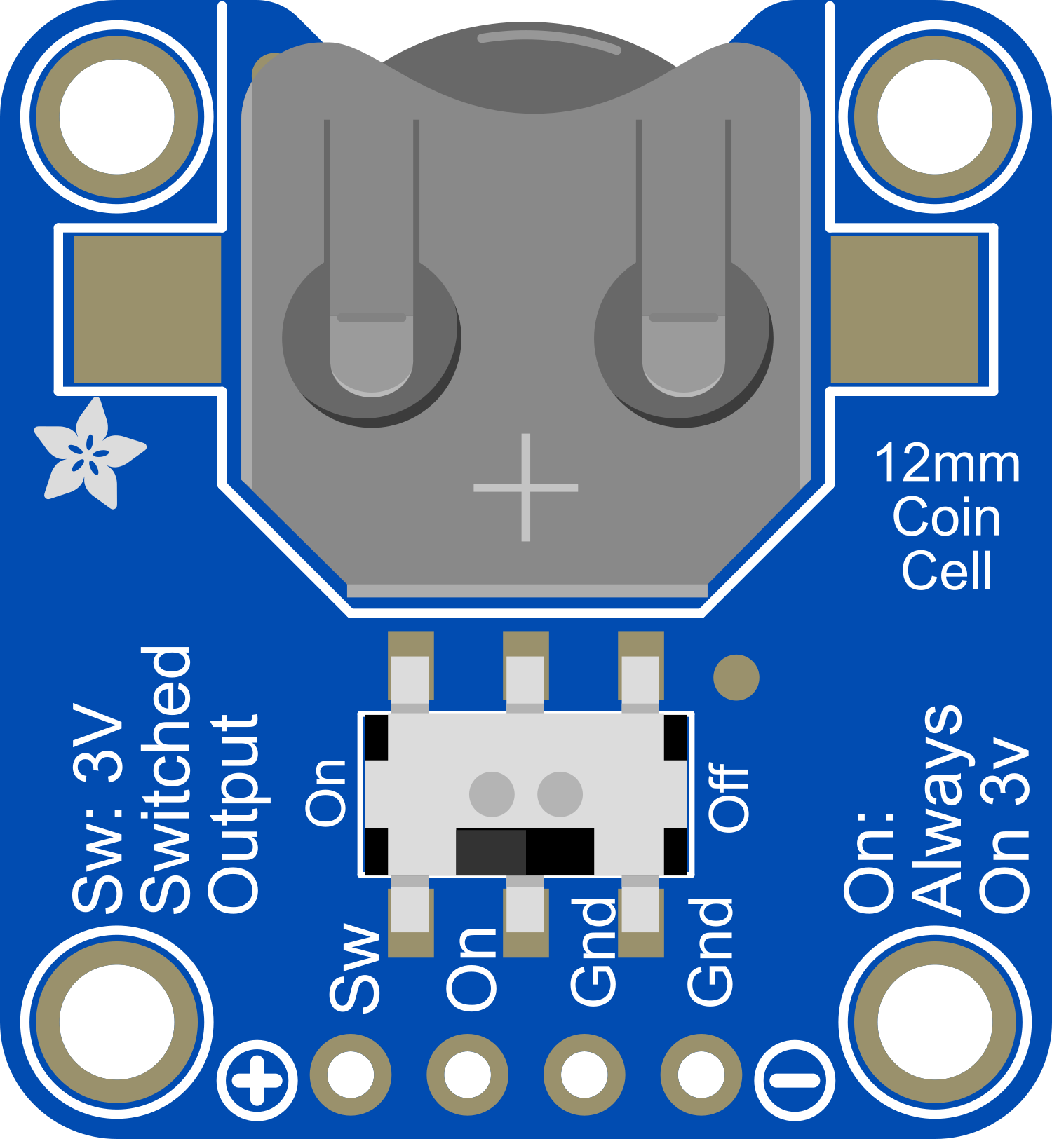
The Adafruit Switched 12mm Coin Cell Breakout is a compact and convenient solution for powering small electronics projects with a 12mm coin cell battery. This breakout board simplifies the connection and management of coin cell batteries, featuring an integrated on/off switch and a voltage regulator. It is ideal for low-power applications, wearable electronics, and when space is at a premium.
Explore Projects Built with Adafruit Switched 12mm Coin Cell Breakout
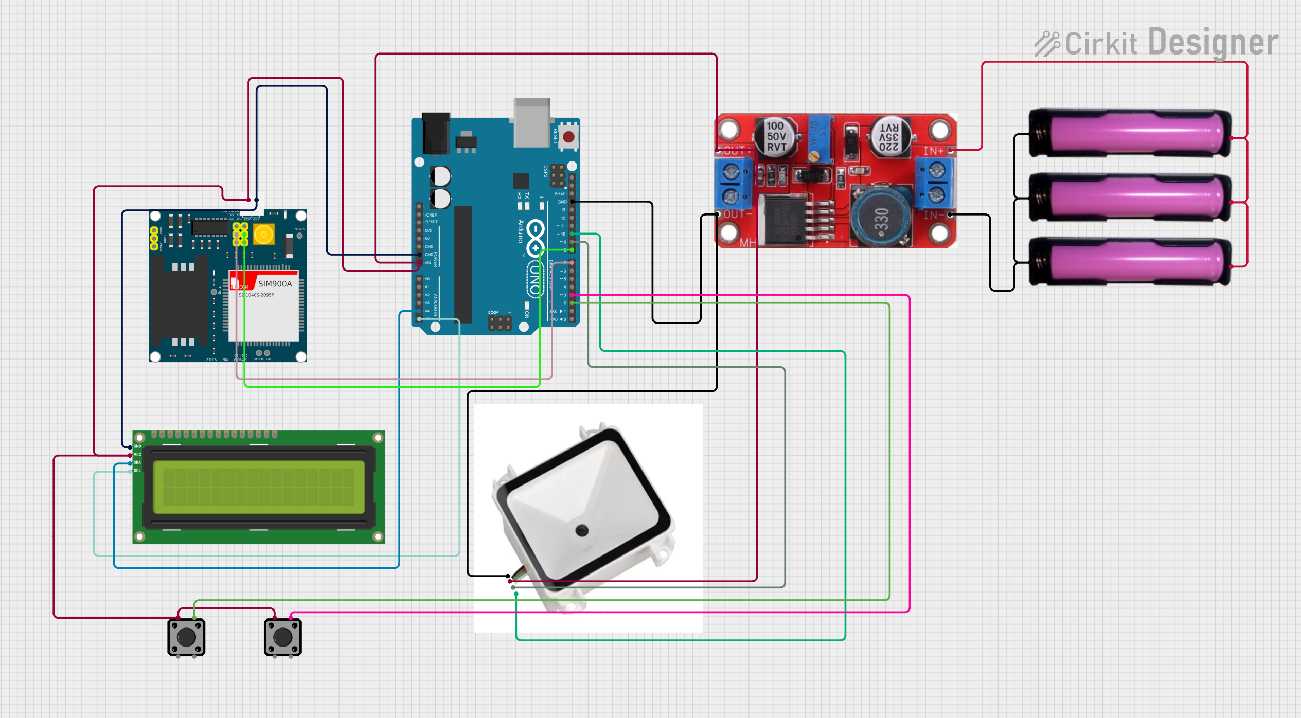
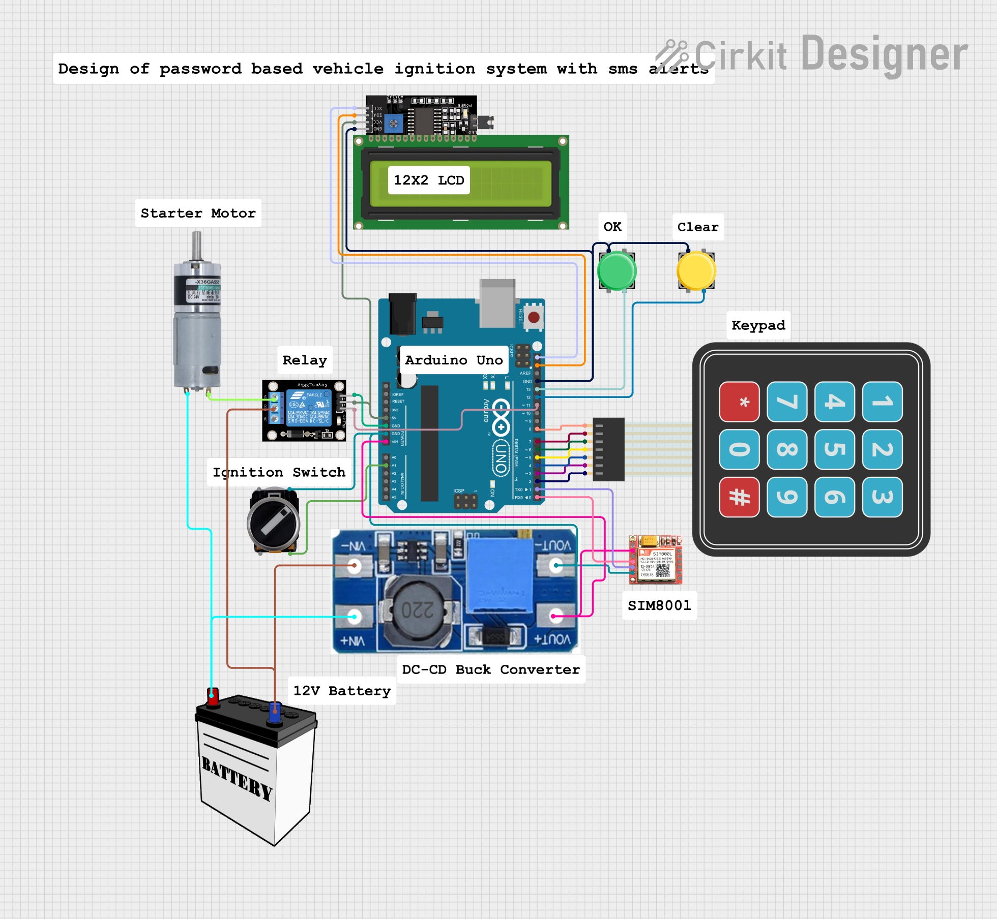

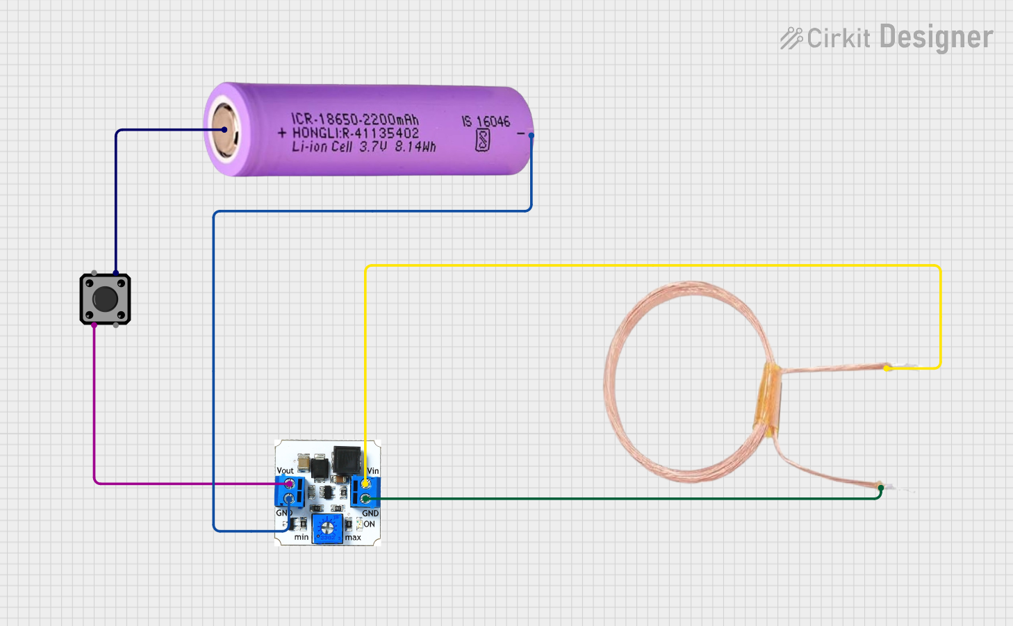
Explore Projects Built with Adafruit Switched 12mm Coin Cell Breakout
Common Applications and Use Cases
- Wearable devices
- Small gadgets and toys
- Portable prototypes
- Backup power for RTC modules
- Quick demonstrations of low-power circuits
Technical Specifications
Key Technical Details
- Battery Compatibility: 12mm diameter coin cell batteries
- Voltage Input: Coin cell battery voltage (typically 3V for CR1220)
- Voltage Output: Regulated voltage (check the specific regulator details)
- Max Current: Dependent on the battery capacity and regulator
- Dimensions: Small footprint to fit in tight spaces
Pin Configuration and Descriptions
| Pin Number | Name | Description |
|---|---|---|
| 1 | VOUT | Regulated voltage output to the circuit |
| 2 | GND | Ground connection |
| 3 | VIN | Voltage input from the coin cell battery |
| 4 | SW | Connection to the integrated on/off switch |
Usage Instructions
How to Use the Component in a Circuit
Insert the Coin Cell Battery:
- Ensure the on/off switch is in the OFF position.
- Insert the 12mm coin cell battery into the holder with the positive side facing up.
Connecting to a Circuit:
- Connect the VOUT pin to the power input of your circuit.
- Connect the GND pin to the ground of your circuit.
Powering On:
- Once the battery and circuit are connected, slide the switch to the ON position to power the circuit.
Important Considerations and Best Practices
- Battery Orientation: Always insert the battery with the correct polarity.
- Switch Handling: Use the switch to turn off the power when the circuit is not in use to conserve battery life.
- Voltage Regulation: Be aware of the voltage regulator's specifications to ensure compatibility with your circuit's voltage requirements.
- Battery Life: Monitor the battery life, as coin cells have limited capacity and may need frequent replacement in high-drain applications.
Troubleshooting and FAQs
Common Issues
Circuit Not Powering On:
- Check if the battery is inserted correctly with the proper polarity.
- Ensure the on/off switch is in the ON position.
- Verify that the battery has sufficient charge.
Insufficient Voltage:
- Confirm that the voltage regulator is functioning correctly.
- Check for any short circuits or overloads that may cause voltage drops.
Solutions and Tips for Troubleshooting
Battery Issues:
- Replace the battery if it is depleted or if the voltage is below the required level for your circuit.
Switch Issues:
- If the switch is not functioning, inspect it for any physical damage or debris that may prevent proper operation.
Regulator Issues:
- If the output voltage is incorrect, ensure that the regulator is not damaged and that it is suitable for the battery and load.
FAQs
Q: Can I use rechargeable coin cell batteries with this breakout?
- A: Yes, as long as they are 12mm in diameter and the voltage matches the regulator's input requirements.
Q: What is the maximum current the breakout can handle?
- A: The maximum current is dependent on the specific coin cell battery and the voltage regulator used. Refer to the datasheets for the battery and regulator for detailed information.
Q: How do I know when to replace the battery?
- A: Monitor the output voltage or observe the performance of your circuit. When the voltage drops or the circuit fails to operate correctly, it's time to replace the battery.
Example Code for Arduino UNO
// Example code to read the voltage from the Adafruit Switched 12mm Coin Cell Breakout

const int batteryPin = A0; // Connect VOUT to analog pin A0 on Arduino

void setup() {
  Serial.begin(9600);
}

void loop() {
  int sensorValue = analogRead(batteryPin); // Read the voltage
  float voltage = sensorValue * (5.0 / 1023.0); // Convert to voltage
  Serial.print("Battery Voltage: ");
  Serial.println(voltage);
  delay(1000); // Wait for a second before reading again
}
Note: This example assumes that the regulated voltage from the breakout is within the range acceptable for the Arduino's analog input. Adjust the code as necessary for the specific voltage regulator used with the breakout.