How to Use GPS NEO-M8N: Examples, Pinouts, and Specs
Introduction
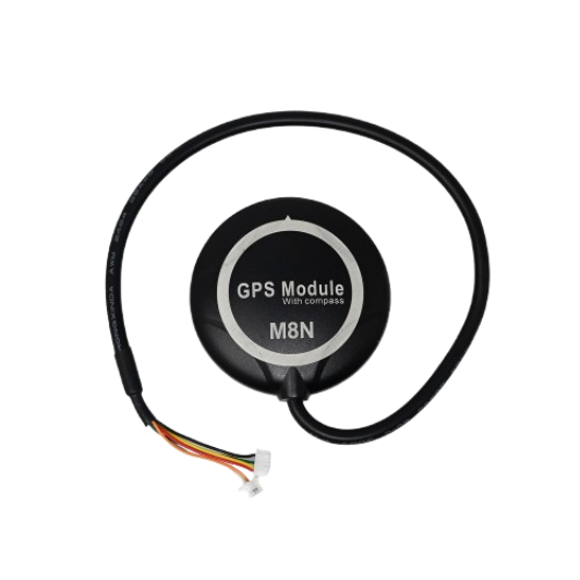
The GPS NEO-M8N is a high-performance GPS module designed to provide accurate positioning and timing information. It supports multiple Global Navigation Satellite Systems (GNSS), including GPS, GLONASS, Galileo, and BeiDou, ensuring reliable and precise location data in various environments. This module is widely used in applications such as navigation systems, robotics, drones, and Internet of Things (IoT) devices.
With its compact design, low power consumption, and advanced features like Assisted GPS (A-GPS) and configurable update rates, the NEO-M8N is an ideal choice for projects requiring robust and efficient location tracking.
Explore Projects Built with GPS NEO-M8N


Explore Projects Built with GPS NEO-M8N
Technical Specifications
Below are the key technical details and pin configuration of the GPS NEO-M8N module:
Key Technical Details
| Parameter | Specification |
|---|---|
| GNSS Support | GPS, GLONASS, Galileo, BeiDou |
| Frequency Bands | L1 (1575.42 MHz) |
| Position Accuracy | 2.5 meters CEP (Circular Error Probable) |
| Update Rate | Up to 10 Hz |
| Supply Voltage | 2.7V to 3.6V |
| Operating Current | ~23 mA (typical) |
| Communication Interfaces | UART, I2C, SPI |
| Antenna | External active/passive antenna support |
| Operating Temperature | -40°C to +85°C |
| Dimensions | 16 x 12.2 x 2.4 mm |
Pin Configuration and Descriptions
| Pin Name | Pin Number | Description |
|---|---|---|
| VCC | 1 | Power supply input (2.7V to 3.6V) |
| GND | 2 | Ground |
| TX | 3 | UART Transmit (data output) |
| RX | 4 | UART Receive (data input) |
| SDA | 5 | I2C Data Line |
| SCL | 6 | I2C Clock Line |
| PPS | 7 | Pulse Per Second output for timing |
| RST | 8 | Reset input (active low) |
| ANT | 9 | Antenna input |
Usage Instructions
How to Use the GPS NEO-M8N in a Circuit
- Power Supply: Connect the VCC pin to a 3.3V power source and the GND pin to ground.
- Communication Interface: Choose a communication protocol (UART, I2C, or SPI) based on your application. For most Arduino projects, UART is commonly used.
- Antenna: Attach an external active or passive antenna to the ANT pin for optimal signal reception.
- Data Reading: Use the TX and RX pins to transmit and receive data. Ensure the baud rate is set to 9600 bps by default (configurable).
- Optional Connections: Use the PPS pin for precise timing applications or the RST pin to reset the module.
Important Considerations and Best Practices
- Antenna Placement: Ensure the antenna has a clear view of the sky for optimal satellite reception.
- Power Supply: Use a stable power source to avoid performance issues.
- Baud Rate Configuration: If needed, configure the baud rate using u-blox's u-center software.
- Interference: Avoid placing the module near high-frequency noise sources to prevent signal degradation.
Example: Connecting GPS NEO-M8N to Arduino UNO
Below is an example of how to interface the GPS NEO-M8N with an Arduino UNO using the UART interface:
Wiring Diagram
| GPS NEO-M8N Pin | Arduino UNO Pin |
|---|---|
| VCC | 3.3V |
| GND | GND |
| TX | RX (Pin 0) |
| RX | TX (Pin 1) |
Arduino Code Example
#include <SoftwareSerial.h>

// Define RX and TX pins for SoftwareSerial
SoftwareSerial gpsSerial(4, 3); // RX = Pin 4, TX = Pin 3

void setup() {
  Serial.begin(9600); // Initialize Serial Monitor at 9600 bps
  gpsSerial.begin(9600); // Initialize GPS module at 9600 bps

  Serial.println("GPS NEO-M8N Test");
}

void loop() {
  // Check if data is available from the GPS module
  while (gpsSerial.available()) {
    char c = gpsSerial.read(); // Read a character from GPS
    Serial.print(c); // Print the character to Serial Monitor
  }
}
Notes:
- Use
SoftwareSerialto avoid conflicts with the Arduino's hardware UART (pins 0 and 1). - Ensure the GPS module is powered and has a clear view of the sky for proper operation.
Troubleshooting and FAQs
Common Issues and Solutions
No GPS Fix:
- Cause: Poor antenna placement or obstructed view of the sky.
- Solution: Place the antenna in an open area with a clear view of the sky.
No Data Output:
- Cause: Incorrect wiring or baud rate mismatch.
- Solution: Verify connections and ensure the baud rate matches the module's configuration.
Intermittent Signal Loss:
- Cause: Electromagnetic interference or unstable power supply.
- Solution: Keep the module away from noise sources and use a stable power source.
Module Not Responding:
- Cause: Incorrect power supply voltage or damaged module.
- Solution: Ensure the supply voltage is within the specified range (2.7V to 3.6V).
FAQs
Q1: Can the NEO-M8N work indoors?
A1: While the module may work indoors, signal reception is significantly reduced. For best results, use it outdoors or near a window.
Q2: How do I change the update rate?
A2: Use the u-blox u-center software to configure the update rate (up to 10 Hz).
Q3: Does the module support 5V logic levels?
A3: No, the NEO-M8N operates at 3.3V logic levels. Use a level shifter if interfacing with 5V systems.
Q4: What type of antenna should I use?
A4: An active antenna is recommended for better performance, but a passive antenna can also be used in strong signal areas.