Cirkit Designer Logo
Cirkit Designer
Your all-in-one circuit design IDE
Home / 
Component Documentation

How to Use ESP32-S3: Examples, Pinouts, and Specs

Image of ESP32-S3
Cirkit Designer LogoDesign with ESP32-S3 in Cirkit Designer

Introduction

The ESP32-S3, manufactured by Automata (Part ID: ESP32), is a powerful and versatile system-on-a-chip (SoC) designed for Internet of Things (IoT) applications. It combines Wi-Fi and Bluetooth Low Energy (BLE) connectivity with a dual-core processor, enhanced AI capabilities, and a wide range of peripherals. The ESP32-S3 is optimized for low-power operation, making it ideal for battery-powered devices and energy-efficient systems.

Explore Projects Built with ESP32-S3

Use Cirkit Designer to design, explore, and prototype these projects online. Some projects support real-time simulation. Click "Open Project" to start designing instantly!
ESP32-S3 Based Automated Watering System with Ultrasonic Sensing and Data Logging
Image of galon otomatis telegram: A project utilizing ESP32-S3 in a practical application
This circuit features an ESP32-S3 microcontroller connected to various peripherals including an HC-SR04 ultrasonic sensor, a water flow sensor, an OLED display, a DS3231 real-time clock (RTC), an SD card module, a water pump, a two-channel relay, and a valve solenoid. The ESP32-S3 manages sensor readings, data logging, and controls the water pump and valve via the relay based on sensor inputs. The circuit is designed for monitoring and controlling water flow, likely in an automated irrigation or fluid management system.
Cirkit Designer LogoOpen Project in Cirkit Designer
ESP32-S3 GPS and Wind Speed Logger with Dual OLED Displays and CAN Bus
Image of esp32-s3-ellipse: A project utilizing ESP32-S3 in a practical application
This circuit features an ESP32-S3 microcontroller interfaced with an SD card module, two OLED displays, a GPS module, and a CAN bus module. The ESP32-S3 records GPS data to the SD card, displays speed on one OLED, and shows wind speed from the CAN bus on the other OLED, providing a comprehensive data logging and display system.
Cirkit Designer LogoOpen Project in Cirkit Designer
ESP32-S3 Based Environmental Monitoring and Control System with Data Logging
Image of ESP32: A project utilizing ESP32-S3 in a practical application
This circuit features an ESP32-S3 microcontroller interfaced with various sensors and modules, including a DHT22 temperature and humidity sensor, an HC-SR04 ultrasonic sensor, an SGP41 VOC and NOx sensor, and an Adafruit INA260 current and power sensor. The ESP32-S3 also controls a DC motor via a relay and communicates with an SD card and an OLED display. An Arduino UNO is used to read inputs from a rotary encoder, and a step-down buck converter is used to regulate voltage from a 12V battery to power the components.
Cirkit Designer LogoOpen Project in Cirkit Designer
ESP32-S3 Based Vibration Detection System with TFT Display and Power Backup
Image of IOT Thesis: A project utilizing ESP32-S3 in a practical application
This circuit features an ESP32-S3 microcontroller connected to various peripherals including an ADXL355 accelerometer, an SW-420 vibration sensor, a buzzer module, and an ILI9341 TFT display. The ESP32-S3 manages sensor inputs and provides output to the display and buzzer. Power management is handled by a 12V to 5V step-down converter, and a UPS ensures uninterrupted power supply, with a rocker switch to control the power flow.
Cirkit Designer LogoOpen Project in Cirkit Designer

Explore Projects Built with ESP32-S3

Use Cirkit Designer to design, explore, and prototype these projects online. Some projects support real-time simulation. Click "Open Project" to start designing instantly!
Image of galon otomatis telegram: A project utilizing ESP32-S3 in a practical application
ESP32-S3 Based Automated Watering System with Ultrasonic Sensing and Data Logging
This circuit features an ESP32-S3 microcontroller connected to various peripherals including an HC-SR04 ultrasonic sensor, a water flow sensor, an OLED display, a DS3231 real-time clock (RTC), an SD card module, a water pump, a two-channel relay, and a valve solenoid. The ESP32-S3 manages sensor readings, data logging, and controls the water pump and valve via the relay based on sensor inputs. The circuit is designed for monitoring and controlling water flow, likely in an automated irrigation or fluid management system.
Cirkit Designer LogoOpen Project in Cirkit Designer
Image of esp32-s3-ellipse: A project utilizing ESP32-S3 in a practical application
ESP32-S3 GPS and Wind Speed Logger with Dual OLED Displays and CAN Bus
This circuit features an ESP32-S3 microcontroller interfaced with an SD card module, two OLED displays, a GPS module, and a CAN bus module. The ESP32-S3 records GPS data to the SD card, displays speed on one OLED, and shows wind speed from the CAN bus on the other OLED, providing a comprehensive data logging and display system.
Cirkit Designer LogoOpen Project in Cirkit Designer
Image of ESP32: A project utilizing ESP32-S3 in a practical application
ESP32-S3 Based Environmental Monitoring and Control System with Data Logging
This circuit features an ESP32-S3 microcontroller interfaced with various sensors and modules, including a DHT22 temperature and humidity sensor, an HC-SR04 ultrasonic sensor, an SGP41 VOC and NOx sensor, and an Adafruit INA260 current and power sensor. The ESP32-S3 also controls a DC motor via a relay and communicates with an SD card and an OLED display. An Arduino UNO is used to read inputs from a rotary encoder, and a step-down buck converter is used to regulate voltage from a 12V battery to power the components.
Cirkit Designer LogoOpen Project in Cirkit Designer
Image of IOT Thesis: A project utilizing ESP32-S3 in a practical application
ESP32-S3 Based Vibration Detection System with TFT Display and Power Backup
This circuit features an ESP32-S3 microcontroller connected to various peripherals including an ADXL355 accelerometer, an SW-420 vibration sensor, a buzzer module, and an ILI9341 TFT display. The ESP32-S3 manages sensor inputs and provides output to the display and buzzer. Power management is handled by a 12V to 5V step-down converter, and a UPS ensures uninterrupted power supply, with a rocker switch to control the power flow.
Cirkit Designer LogoOpen Project in Cirkit Designer

Common Applications and Use Cases

  • Smart home devices (e.g., smart lights, thermostats, and security systems)
  • Wearable technology and fitness trackers
  • Industrial IoT (IIoT) applications
  • AI and machine learning at the edge
  • Wireless sensor networks
  • Robotics and automation systems
  • Real-time data processing and streaming

Technical Specifications

Key Technical Details

Parameter Specification
Processor Dual-core Xtensa® LX7, up to 240 MHz
Wireless Connectivity Wi-Fi 802.11 b/g/n (2.4 GHz), Bluetooth 5.0 LE
AI Capabilities Vector extensions for AI acceleration
Flash Memory Up to 16 MB external flash
RAM 512 KB internal SRAM, support for external PSRAM
GPIO Pins 45 GPIOs (configurable for various functions)
Operating Voltage 3.0V to 3.6V
Power Consumption Ultra-low power modes (Deep Sleep: ~10 µA)
Peripherals SPI, I2C, I2S, UART, ADC, DAC, PWM, SDIO, CAN, Ethernet MAC, USB OTG
Temperature Range -40°C to +85°C
Package QFN48 (7x7 mm)

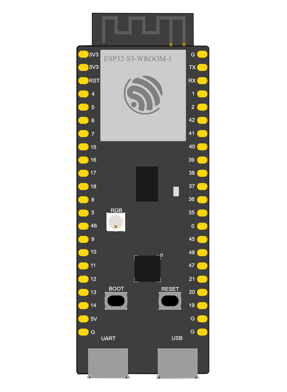
Pin Configuration and Descriptions

The ESP32-S3 has a flexible pinout with multiple functions assignable to each pin. Below is a summary of key pins:

Pin Number Pin Name Functionality
1 GPIO0 General-purpose I/O, boot mode selection
2 GPIO1 General-purpose I/O, UART TX
3 GPIO2 General-purpose I/O, ADC, touch sensor
4 GPIO3 General-purpose I/O, UART RX
5 GPIO4 General-purpose I/O, PWM, ADC
6 GPIO5 General-purpose I/O, SPI, PWM
7 EN Chip enable (active high)
8 3V3 Power supply (3.3V)
9 GND Ground
10 GPIO21 I2C SDA, general-purpose I/O
11 GPIO22 I2C SCL, general-purpose I/O
12 GPIO23 SPI MOSI, general-purpose I/O

Note: Refer to the full datasheet for a complete pinout and alternate functions.

Usage Instructions

How to Use the ESP32-S3 in a Circuit

  1. Power Supply: Provide a stable 3.3V power supply to the 3V3 pin and connect GND to ground.
  2. Boot Mode: To enter bootloader mode for programming, hold GPIO0 low while resetting the chip.
  3. Peripherals: Connect peripherals (e.g., sensors, actuators) to the GPIO pins. Use appropriate pull-up or pull-down resistors as needed.
  4. Programming: Use a USB-to-serial adapter to connect the ESP32-S3 to your computer. Flash firmware using tools like esptool.py or the Arduino IDE.

Important Considerations and Best Practices

  • Power Management: Use the deep sleep mode to minimize power consumption in battery-powered applications.
  • GPIO Voltage Levels: Ensure all GPIO pins operate within the 3.3V logic level to avoid damage.
  • Decoupling Capacitors: Place decoupling capacitors (e.g., 0.1 µF) near the power pins to reduce noise.
  • Antenna Placement: For optimal wireless performance, ensure the onboard antenna is not obstructed by metal or other conductive materials.

Example: Connecting the ESP32-S3 to an Arduino UNO

The ESP32-S3 can be programmed using the Arduino IDE. Below is an example of a basic Wi-Fi connection sketch:

#include <WiFi.h> // Include the Wi-Fi library for ESP32

// Replace with your network credentials
const char* ssid = "Your_SSID";
const char* password = "Your_PASSWORD";

void setup() {
  Serial.begin(115200); // Initialize serial communication
  delay(1000);

  Serial.println("Connecting to Wi-Fi...");
  WiFi.begin(ssid, password); // Start Wi-Fi connection

  while (WiFi.status() != WL_CONNECTED) {
    delay(500);
    Serial.print("."); // Print dots while connecting
  }

  Serial.println("\nWi-Fi connected!");
  Serial.print("IP Address: ");
  Serial.println(WiFi.localIP()); // Print the assigned IP address
}

void loop() {
  // Add your main code here
}

Tip: Install the ESP32 board package in the Arduino IDE before uploading the code.

Troubleshooting and FAQs

Common Issues and Solutions

  1. ESP32-S3 Not Connecting to Wi-Fi

    • Solution: Double-check the SSID and password. Ensure the router is operating on the 2.4 GHz band (not 5 GHz).
  2. Device Not Detected by Computer

    • Solution: Verify the USB cable is functional and supports data transfer. Install the correct USB-to-serial drivers.
  3. Random Resets or Instability

    • Solution: Ensure the power supply is stable and capable of providing sufficient current (at least 500 mA).
  4. GPIO Pin Not Responding

    • Solution: Check if the pin is configured correctly in the code. Avoid using reserved pins.

FAQs

  • Q: Can the ESP32-S3 run AI models?

    • A: Yes, the ESP32-S3 supports AI acceleration with vector extensions, making it suitable for lightweight AI tasks.
  • Q: What is the maximum Wi-Fi range?

    • A: The range depends on environmental factors but typically extends up to 100 meters in open space.
  • Q: Can I use the ESP32-S3 with a 5V power supply?

    • A: No, the ESP32-S3 operates at 3.3V. Use a voltage regulator if your power source is 5V.
  • Q: How do I update the firmware?

    • A: Use tools like esptool.py or the Arduino IDE to flash new firmware via the USB interface.

This concludes the documentation for the ESP32-S3. For further details, refer to the official datasheet and application notes provided by Automata.