How to Use LiDAR VL53L0X: Examples, Pinouts, and Specs
Introduction
The VL53L0X is a compact, high-performance time-of-flight (ToF) laser-ranging sensor manufactured by STMicroelectronics (Part ID: VL53L0CXV0DH/1). It measures distances up to 2 meters with millimeter-level accuracy by calculating the time it takes for emitted laser light to reflect back from a target object. This sensor is designed for low-power operation and is ideal for applications requiring precise distance measurements.
Explore Projects Built with LiDAR VL53L0X


Explore Projects Built with LiDAR VL53L0X
Common Applications
- Robotics: Obstacle detection and navigation
- Drones: Altitude measurement and collision avoidance
- Automation: Proximity sensing and object detection
- Consumer Electronics: Gesture recognition and presence detection
- IoT Devices: Smart home automation and security systems
Technical Specifications
The VL53L0X is a highly integrated module that includes a laser emitter, a single-photon avalanche diode (SPAD) array, and a microcontroller for processing. Below are its key technical details:
Key Specifications
| Parameter | Value |
|---|---|
| Operating Voltage | 2.6V to 3.5V |
| Communication Interface | I²C (up to 400 kHz) |
| Measurement Range | 30 mm to 2000 mm |
| Accuracy | ±3% (typical) |
| Field of View (FoV) | 25° |
| Operating Temperature | -20°C to +70°C |
| Power Consumption | 20 mW (typical in active mode) |
| Dimensions | 4.4 mm x 2.4 mm x 1.0 mm |
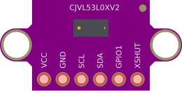
Pin Configuration
The VL53L0X module has six pins, as described in the table below:
| Pin Name | Pin Number | Description |
|---|---|---|
| VIN | 1 | Power supply input (2.6V to 5.5V) |
| GND | 2 | Ground connection |
| SDA | 3 | I²C data line |
| SCL | 4 | I²C clock line |
| XSHUT | 5 | Shutdown pin (active low) |
| GPIO1 | 6 | Interrupt output (optional, configurable) |
Usage Instructions
How to Use the VL53L0X in a Circuit
- Power Supply: Connect the VIN pin to a 3.3V or 5V power source and the GND pin to ground.
- I²C Communication: Connect the SDA and SCL pins to the corresponding I²C pins on your microcontroller. Use pull-up resistors (typically 4.7 kΩ) on both lines if not already provided.
- Shutdown Control: Use the XSHUT pin to enable or disable the sensor. Pull it low to shut down the sensor and high (or leave it floating) to enable it.
- Interrupts (Optional): If needed, connect the GPIO1 pin to a microcontroller pin to handle interrupts.
Important Considerations
- Ambient Light: Avoid direct exposure to strong ambient light sources, as they may interfere with measurements.
- Reflective Surfaces: Highly reflective or transparent surfaces may affect accuracy.
- I²C Address: The default I²C address is 0x29. If using multiple sensors, you must change their addresses by toggling the XSHUT pin and reinitializing each sensor.
Example Code for Arduino UNO
Below is an example of how to interface the VL53L0X with an Arduino UNO using the Adafruit VL53L0X library:
#include <Wire.h>
#include <Adafruit_VL53L0X.h>

// Create an instance of the VL53L0X sensor
Adafruit_VL53L0X lox = Adafruit_VL53L0X();

void setup() {
  Serial.begin(9600); // Initialize serial communication
  while (!Serial) {
    delay(10); // Wait for Serial Monitor to open
  }

  Serial.println("VL53L0X Test");

  // Initialize the sensor
  if (!lox.begin()) {
    Serial.println("Failed to initialize VL53L0X! Check wiring.");
    while (1);
  }
  Serial.println("VL53L0X initialized successfully.");
}

void loop() {
  VL53L0X_RangingMeasurementData_t measure;

  // Perform a ranging measurement
  lox.rangingTest(&measure, false);

  // Check if the measurement is valid
  if (measure.RangeStatus != 4) { // 4 indicates an out-of-range error
    Serial.print("Distance (mm): ");
    Serial.println(measure.RangeMilliMeter);
  } else {
    Serial.println("Out of range");
  }

  delay(100); // Wait 100ms before the next measurement
}
Best Practices
- Use decoupling capacitors (e.g., 0.1 µF) near the VIN pin to stabilize the power supply.
- Keep I²C lines as short as possible to minimize noise.
- Mount the sensor securely to avoid misalignment during operation.
Troubleshooting and FAQs
Common Issues
Sensor Not Detected on I²C Bus
- Cause: Incorrect wiring or missing pull-up resistors.
- Solution: Verify connections and ensure SDA and SCL lines have pull-up resistors.
Inaccurate Distance Measurements
- Cause: Strong ambient light or reflective surfaces.
- Solution: Reduce ambient light or reposition the sensor to avoid reflective surfaces.
Out-of-Range Errors
- Cause: Object is too close (<30 mm) or too far (>2000 mm).
- Solution: Ensure the object is within the sensor's measurement range.
Interference with Multiple Sensors
- Cause: All sensors have the same default I²C address.
- Solution: Use the XSHUT pin to assign unique I²C addresses to each sensor.
FAQs
Q: Can the VL53L0X measure through glass?
A: The sensor can measure through transparent glass, but accuracy may be reduced due to reflections.
Q: What is the maximum I²C cable length?
A: For reliable communication, keep the I²C cable length under 50 cm. Use shielded cables for longer distances.
Q: Can I use the VL53L0X with a 5V microcontroller?
A: Yes, the sensor is 5V-tolerant on the VIN pin, but the I²C lines require level shifting if the microcontroller operates at 5V.
Q: How do I reset the sensor?
A: Pull the XSHUT pin low for at least 1 ms, then pull it high to reset the sensor.
By following this documentation, you can effectively integrate the VL53L0X into your projects and troubleshoot common issues.