How to Use LM 358 Module OP-AMP: Examples, Pinouts, and Specs
Introduction
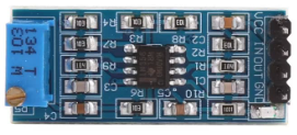
The LM358 is a dual operational amplifier (op-amp) module designed for a wide range of analog signal processing tasks. It can operate from a single power supply or dual power supplies, making it highly versatile. The LM358 features low power consumption, high gain, and a wide bandwidth, making it ideal for applications such as signal conditioning, filtering, and amplification. Its compact design and ease of use make it a popular choice for both hobbyists and professionals.
Explore Projects Built with LM 358 Module OP-AMP
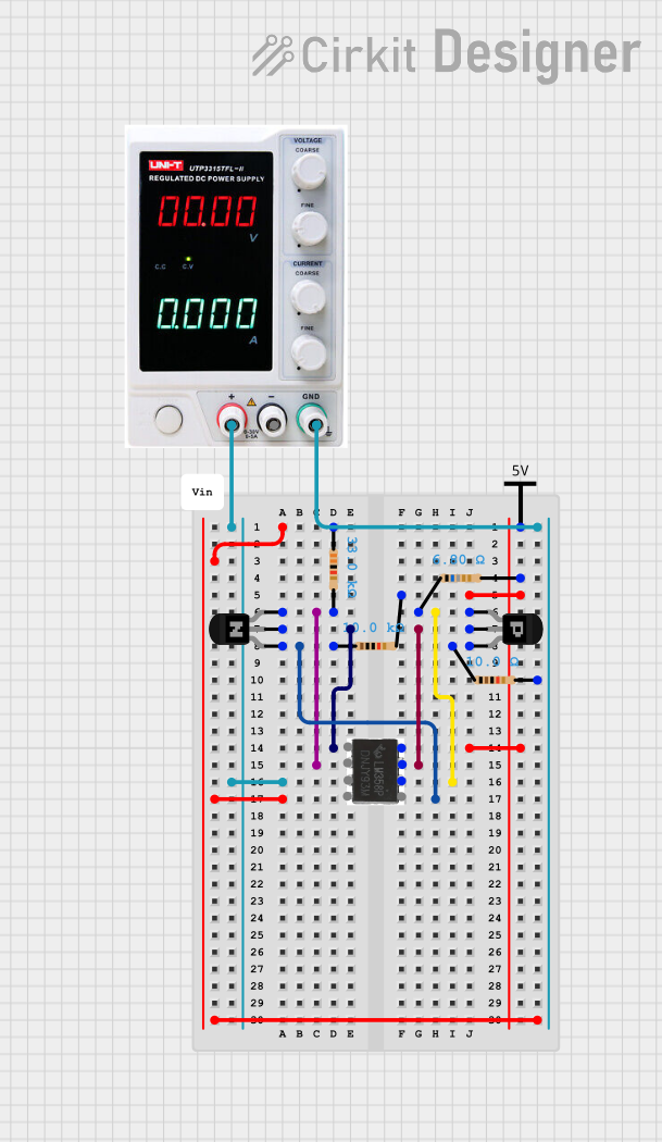
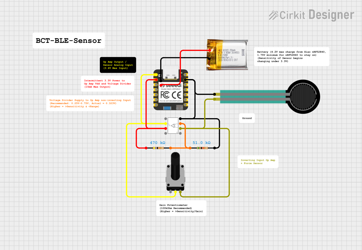
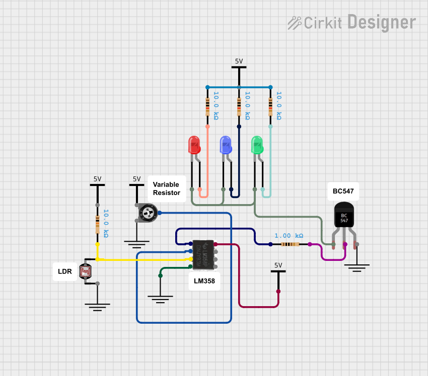
Explore Projects Built with LM 358 Module OP-AMP
Common Applications and Use Cases
- Signal amplification in audio and sensor circuits
- Analog filtering for noise reduction
- Voltage comparators
- Signal conditioning for microcontroller inputs
- Oscillator circuits and waveform generation
Technical Specifications
Key Technical Details
- Operating Voltage Range: 3V to 32V (single supply) or ±1.5V to ±16V (dual supply)
- Input Offset Voltage: 2mV (typical)
- Input Bias Current: 45nA (typical)
- Gain Bandwidth Product: 1 MHz
- Output Voltage Swing: 0V to (Vcc - 1.5V)
- Supply Current: 0.7mA (typical)
- Operating Temperature Range: 0°C to 70°C
- Package Type: DIP-8 or SOIC-8 (depending on the module)
Pin Configuration and Descriptions
The LM358 module typically uses the standard DIP-8 package. Below is the pinout and description:
| Pin Number | Pin Name | Description |
|---|---|---|
| 1 | Output 1 | Output of the first operational amplifier |
| 2 | Inverting Input 1 | Inverting input of the first operational amplifier |
| 3 | Non-Inverting Input 1 | Non-inverting input of the first operational amplifier |
| 4 | V- (GND) | Negative power supply or ground connection |
| 5 | Non-Inverting Input 2 | Non-inverting input of the second operational amplifier |
| 6 | Inverting Input 2 | Inverting input of the second operational amplifier |
| 7 | Output 2 | Output of the second operational amplifier |
| 8 | V+ (Vcc) | Positive power supply connection |
Usage Instructions
How to Use the LM358 Module in a Circuit
- Power Supply: Connect the V+ pin (Pin 8) to the positive voltage supply and the V- pin (Pin 4) to ground (for single supply) or a negative voltage (for dual supply).
- Input Connections: Connect the signal to be amplified to the non-inverting input (Pin 3 or Pin 5) or the inverting input (Pin 2 or Pin 6), depending on the desired configuration (non-inverting or inverting amplifier).
- Output: The amplified signal will be available at the corresponding output pin (Pin 1 or Pin 7).
- Feedback Resistor: Use appropriate resistors between the output and input pins to set the gain of the amplifier.
- Bypass Capacitor: Place a decoupling capacitor (e.g., 0.1µF) across the power supply pins to reduce noise.
Important Considerations and Best Practices
- Ensure the input voltage does not exceed the supply voltage range to avoid damage.
- Use proper grounding techniques to minimize noise and interference.
- For high-frequency applications, consider adding a small capacitor in parallel with the feedback resistor to improve stability.
- Avoid driving heavy loads directly from the output; use a buffer if necessary.
Example: Connecting LM358 to an Arduino UNO
The LM358 can be used to amplify an analog signal (e.g., from a sensor) before feeding it into an Arduino UNO's analog input. Below is an example circuit and code:
Circuit Description
- Connect the LM358's V+ pin to the Arduino's 5V pin and the V- pin to GND.
- Connect the sensor output to the non-inverting input (Pin 3).
- Use a feedback resistor and a resistor to ground to set the gain.
- Connect the LM358's output (Pin 1) to an analog input pin on the Arduino (e.g., A0).
Arduino Code Example
// LM358 Amplifier Example with Arduino UNO
// Reads an amplified analog signal and prints the value to the Serial Monitor

const int analogPin = A0; // Analog pin connected to LM358 output

void setup() {
  Serial.begin(9600); // Initialize serial communication at 9600 baud
}

void loop() {
  int sensorValue = analogRead(analogPin); // Read the amplified signal
  float voltage = sensorValue * (5.0 / 1023.0); // Convert to voltage
  Serial.print("Amplified Voltage: ");
  Serial.print(voltage);
  Serial.println(" V");
  delay(500); // Wait for 500ms before the next reading
}
Troubleshooting and FAQs
Common Issues and Solutions
No Output Signal:
- Check the power supply connections (V+ and V-).
- Verify that the input signal is within the acceptable range.
- Ensure the feedback resistor is properly connected.
Distorted Output:
- Check if the output is saturating (exceeding the supply voltage range).
- Reduce the input signal amplitude or adjust the gain.
High Noise Levels:
- Add a bypass capacitor across the power supply pins.
- Use shielded cables for input signals.
Overheating:
- Ensure the module is not driving a load beyond its capacity.
- Verify that the supply voltage is within the specified range.
FAQs
Q: Can the LM358 amplify AC signals?
A: Yes, the LM358 can amplify AC signals. Use coupling capacitors to block DC components if necessary.
Q: What is the maximum gain I can achieve with the LM358?
A: The gain is determined by the feedback resistor configuration. However, for stable operation, avoid excessively high gains.
Q: Can I use the LM358 for audio applications?
A: Yes, the LM358 is suitable for basic audio amplification, but it may not provide high-fidelity performance.
Q: Is the LM358 compatible with 3.3V systems?
A: Yes, the LM358 can operate with a supply voltage as low as 3V, making it compatible with 3.3V systems.