Cirkit Designer Logo
Cirkit Designer
Your all-in-one circuit design IDE
Home / 
Component Documentation

How to Use PS2 Joystick: Examples, Pinouts, and Specs

Image of PS2 Joystick
Cirkit Designer LogoDesign with PS2 Joystick in Cirkit Designer

Introduction

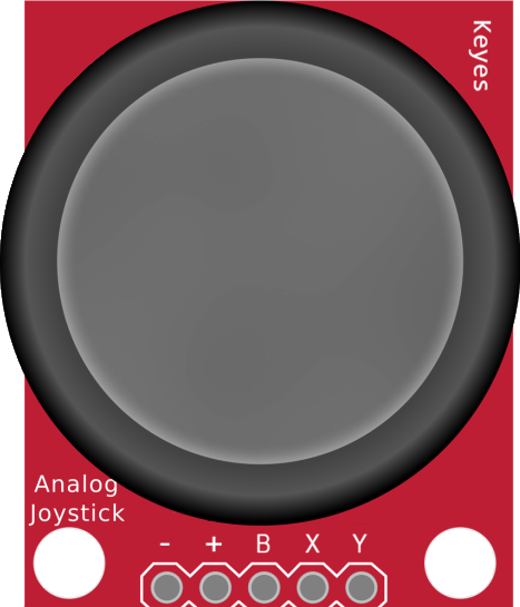
The Keyes PS2 Joystick with Button is an input device designed for precise control in video games, robotics, and other interactive applications. It features two analog potentiometers for X and Y directional movement and a tactile push-button for additional functionality. The joystick is compact, easy to use, and compatible with microcontrollers like Arduino, making it a popular choice for hobbyists and developers.

Explore Projects Built with PS2 Joystick

Use Cirkit Designer to design, explore, and prototype these projects online. Some projects support real-time simulation. Click "Open Project" to start designing instantly!
Raspberry Pi Pico-based PS2 Controller Emulator with ADS1115 Analog Input
Image of PS2Pico: A project utilizing PS2 Joystick in a practical application
This circuit appears to be a game controller interface that uses a Raspberry Pi Pico microcontroller to emulate a PS2 controller, interfacing with a PS2 joystick and a PS2 console cable. The ADS1115 analog-to-digital converter is used to read the joystick's analog signals, and the microcontroller's SPI and I2C interfaces are utilized for communication with the PS2 console and the ADS1115, respectively. Additionally, an NPN transistor and a resistor are configured to handle the PS2 controller's acknowledge signal.
Cirkit Designer LogoOpen Project in Cirkit Designer
Arduino Nano Joystick-Controlled Bluetooth Module with Battery Power
Image of padelpro transmitter: A project utilizing PS2 Joystick in a practical application
This circuit is a wireless joystick controller that uses an Arduino Nano to read analog signals from a KY-023 Dual Axis Joystick Module and transmits the data via an HC-05 Bluetooth Module. The system is powered by a 18650 Li-Ion battery with a rocker switch for power control.
Cirkit Designer LogoOpen Project in Cirkit Designer
Wireless Joystick-Controlled Interface with Arduino Nano and NRF24L01
Image of Transmitter 11: A project utilizing PS2 Joystick in a practical application
This circuit features an Arduino Nano interfaced with a KY-023 Dual Axis Joystick Module for analog input, and an NRF24L01 module for wireless communication. The joystick provides x and y-axis control signals to the Arduino's analog inputs and a switch signal to a digital input, while the NRF24L01 enables the Arduino to communicate with other devices wirelessly. The 2x 18650 batteries supply power to the Arduino, which in turn powers the joystick and the NRF24L01 module.
Cirkit Designer LogoOpen Project in Cirkit Designer
Arduino Nano-Based Wireless Input Controller with Joysticks and Sensors
Image of TRANSMITTER: A project utilizing PS2 Joystick in a practical application
This is a multifunctional interactive device featuring dual-axis control via PS2 joysticks, visual feedback through an OLED display, and wireless communication using an NRF24L01 module. It includes a piezo buzzer for sound, tactile buttons for additional user input, rotary potentiometers for analog control, and an MPU-6050 for motion sensing. The Arduino Nano serves as the central processing unit, coordinating input and output functions, with capacitors for power stability.
Cirkit Designer LogoOpen Project in Cirkit Designer

Explore Projects Built with PS2 Joystick

Use Cirkit Designer to design, explore, and prototype these projects online. Some projects support real-time simulation. Click "Open Project" to start designing instantly!
Image of PS2Pico: A project utilizing PS2 Joystick in a practical application
Raspberry Pi Pico-based PS2 Controller Emulator with ADS1115 Analog Input
This circuit appears to be a game controller interface that uses a Raspberry Pi Pico microcontroller to emulate a PS2 controller, interfacing with a PS2 joystick and a PS2 console cable. The ADS1115 analog-to-digital converter is used to read the joystick's analog signals, and the microcontroller's SPI and I2C interfaces are utilized for communication with the PS2 console and the ADS1115, respectively. Additionally, an NPN transistor and a resistor are configured to handle the PS2 controller's acknowledge signal.
Cirkit Designer LogoOpen Project in Cirkit Designer
Image of padelpro transmitter: A project utilizing PS2 Joystick in a practical application
Arduino Nano Joystick-Controlled Bluetooth Module with Battery Power
This circuit is a wireless joystick controller that uses an Arduino Nano to read analog signals from a KY-023 Dual Axis Joystick Module and transmits the data via an HC-05 Bluetooth Module. The system is powered by a 18650 Li-Ion battery with a rocker switch for power control.
Cirkit Designer LogoOpen Project in Cirkit Designer
Image of Transmitter 11: A project utilizing PS2 Joystick in a practical application
Wireless Joystick-Controlled Interface with Arduino Nano and NRF24L01
This circuit features an Arduino Nano interfaced with a KY-023 Dual Axis Joystick Module for analog input, and an NRF24L01 module for wireless communication. The joystick provides x and y-axis control signals to the Arduino's analog inputs and a switch signal to a digital input, while the NRF24L01 enables the Arduino to communicate with other devices wirelessly. The 2x 18650 batteries supply power to the Arduino, which in turn powers the joystick and the NRF24L01 module.
Cirkit Designer LogoOpen Project in Cirkit Designer
Image of TRANSMITTER: A project utilizing PS2 Joystick in a practical application
Arduino Nano-Based Wireless Input Controller with Joysticks and Sensors
This is a multifunctional interactive device featuring dual-axis control via PS2 joysticks, visual feedback through an OLED display, and wireless communication using an NRF24L01 module. It includes a piezo buzzer for sound, tactile buttons for additional user input, rotary potentiometers for analog control, and an MPU-6050 for motion sensing. The Arduino Nano serves as the central processing unit, coordinating input and output functions, with capacitors for power stability.
Cirkit Designer LogoOpen Project in Cirkit Designer

Common Applications and Use Cases

  • Game controllers and simulators
  • Robotic control systems
  • Camera gimbal control
  • DIY projects requiring analog input
  • Interactive art installations

Technical Specifications

Below are the key technical details of the Keyes PS2 Joystick with Button:

Parameter Specification
Operating Voltage 3.3V - 5V
Output Type Analog (X, Y axes) and Digital (Button)
X-Axis Range 0V to Vcc (centered at ~Vcc/2)
Y-Axis Range 0V to Vcc (centered at ~Vcc/2)
Button Output Digital (Active Low)
Dimensions 34mm x 26mm x 32mm
Interface Type 5-pin header

Pin Configuration and Descriptions

The PS2 Joystick module has a 5-pin header for interfacing. The table below describes each pin:

Pin Name Description
1 GND Ground connection
2 +5V Power supply (3.3V to 5V)
3 VRx Analog output for X-axis movement (0V to Vcc, centered at ~Vcc/2)
4 VRy Analog output for Y-axis movement (0V to Vcc, centered at ~Vcc/2)
5 SW Digital output for the push-button (Active Low: 0V when pressed, Vcc otherwise)

Usage Instructions

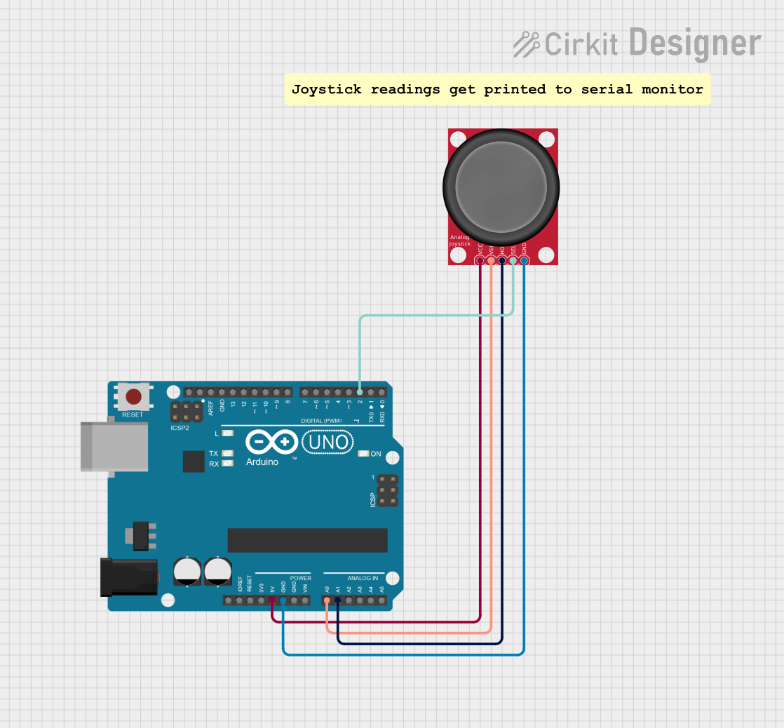
How to Use the Component in a Circuit

  1. Power the Joystick: Connect the +5V pin to the 5V output of your microcontroller and the GND pin to ground.
  2. Read Analog Outputs: Connect the VRx and VRy pins to the analog input pins of your microcontroller to read the X and Y axis values.
  3. Read Button State: Connect the SW pin to a digital input pin to detect button presses.
  4. Pull-Up Resistor for Button: If the microcontroller does not have an internal pull-up resistor, add an external pull-up resistor (e.g., 10kΩ) to the SW pin.

Important Considerations and Best Practices

  • Voltage Compatibility: Ensure the joystick's operating voltage matches your microcontroller's input voltage (3.3V or 5V).
  • Debouncing the Button: Use software debouncing to handle any noise or false triggers from the push-button.
  • Center Calibration: The joystick's analog outputs are centered at approximately half the supply voltage when in the neutral position. Account for this in your code.
  • Avoid Over-Pressing: Excessive force on the joystick or button may damage the module.

Example Code for Arduino UNO

Below is an example Arduino sketch to read the joystick's X, Y, and button states:

// Define pin connections
const int VRxPin = A0; // X-axis connected to analog pin A0
const int VRyPin = A1; // Y-axis connected to analog pin A1
const int SWPin = 2;   // Button connected to digital pin 2

void setup() {
  // Initialize serial communication for debugging
  Serial.begin(9600);

  // Configure the button pin as input with an internal pull-up resistor
  pinMode(SWPin, INPUT_PULLUP);
}

void loop() {
  // Read the X and Y axis values (0 to 1023)
  int xValue = analogRead(VRxPin);
  int yValue = analogRead(VRyPin);

  // Read the button state (LOW when pressed, HIGH otherwise)
  int buttonState = digitalRead(SWPin);

  // Print the values to the Serial Monitor
  Serial.print("X: ");
  Serial.print(xValue);
  Serial.print(" | Y: ");
  Serial.print(yValue);
  Serial.print(" | Button: ");
  Serial.println(buttonState == LOW ? "Pressed" : "Released");

  // Add a small delay for stability
  delay(100);
}

Troubleshooting and FAQs

Common Issues and Solutions

  1. Joystick Outputs Not Centered

    • Cause: The joystick may not be perfectly calibrated.
    • Solution: In your code, account for small deviations from the expected center value (e.g., ±10 units).
  2. Button Not Responding

    • Cause: Missing pull-up resistor or incorrect wiring.
    • Solution: Ensure the SW pin is connected to a pull-up resistor (internal or external).
  3. No Analog Output

    • Cause: Incorrect power supply or damaged module.
    • Solution: Verify the power connections and ensure the module is receiving 3.3V or 5V.
  4. Erratic Readings

    • Cause: Electrical noise or loose connections.
    • Solution: Use shorter wires, secure connections, and add decoupling capacitors if necessary.

FAQs

Q: Can I use the joystick with a Raspberry Pi?
A: Yes, the joystick can be used with a Raspberry Pi. Connect the analog outputs to an ADC (Analog-to-Digital Converter) module, as the Raspberry Pi lacks built-in analog input pins.

Q: What is the lifespan of the joystick?
A: The joystick is designed for long-term use, but its lifespan depends on the frequency and intensity of use. Avoid excessive force to prolong its life.

Q: Can I use the joystick with 3.3V systems?
A: Yes, the joystick is compatible with 3.3V systems. Ensure all connections and microcontroller pins are configured accordingly.

Q: How do I debounce the button in software?
A: Implement a delay (e.g., 50ms) after detecting a button press to filter out noise or false triggers.