How to Use CC2530: Examples, Pinouts, and Specs
Introduction
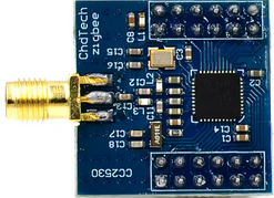
The CC2530, manufactured by Texas Instruments, is a low-power, 2.4 GHz system-on-chip (SoC) designed for Zigbee and IEEE 802.15.4 applications. It combines a high-performance microcontroller, a robust radio transceiver, and a variety of peripherals into a single chip. This makes it an ideal choice for wireless sensor networks, home automation, industrial monitoring, and other low-power wireless communication applications.
Explore Projects Built with CC2530


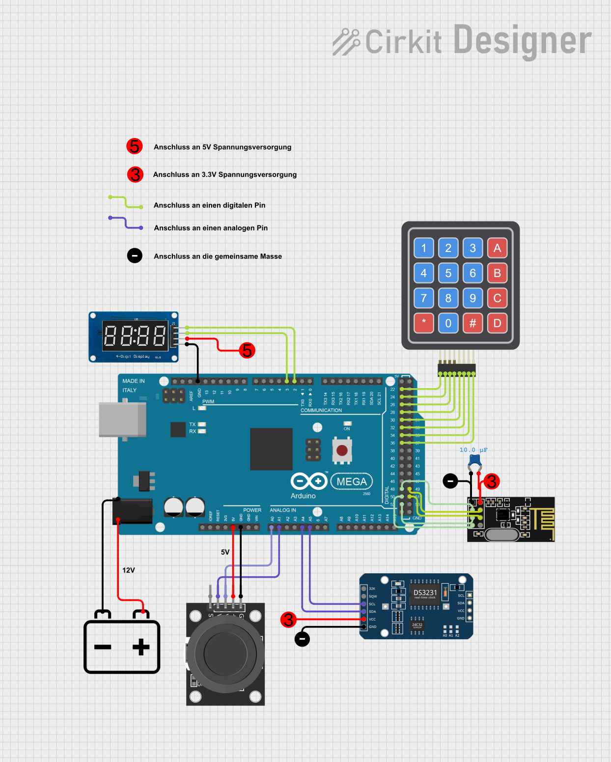
Explore Projects Built with CC2530
Common Applications
- Zigbee-based home automation systems
- Wireless sensor networks
- Smart lighting solutions
- Industrial monitoring and control
- Internet of Things (IoT) devices
Technical Specifications
The CC2530 is a highly integrated SoC with the following key technical specifications:
| Parameter | Value |
|---|---|
| Operating Frequency | 2.4 GHz (IEEE 802.15.4 compliant) |
| Microcontroller Core | 8051-compatible, 8-bit CPU |
| Flash Memory | 8 KB, 16 KB, 32 KB, or 256 KB (depending on variant) |
| RAM | 8 KB |
| Operating Voltage Range | 2.0 V to 3.6 V |
| Transmit Power | Up to +4.5 dBm |
| Receiver Sensitivity | -97 dBm |
| Communication Protocols | Zigbee, IEEE 802.15.4 |
| GPIO Pins | Up to 21 configurable GPIOs |
| Peripherals | UART, SPI, I2C, ADC, Timers, Watchdog Timer |
| Power Consumption (Active) | 24 mA (TX at 1 dBm), 20 mA (RX mode) |
| Power Consumption (Sleep) | < 1 µA |
| Package Options | QFN-40, QFN-48 |
Pin Configuration
The CC2530 is available in QFN-40 and QFN-48 packages. Below is the pin configuration for the QFN-40 package:
| Pin Number | Pin Name | Description |
|---|---|---|
| 1 | VDD | Power supply (2.0 V to 3.6 V) |
| 2 | GND | Ground |
| 3 | P0.0 | GPIO, ADC input, or peripheral function |
| 4 | P0.1 | GPIO, ADC input, or peripheral function |
| 5 | P0.2 | GPIO, ADC input, or peripheral function |
| ... | ... | ... (Refer to the datasheet for details) |
| 40 | RESET_N | Active-low reset input |
For the full pinout and descriptions, refer to the official datasheet.
Usage Instructions
How to Use the CC2530 in a Circuit
- Power Supply: Connect the VDD pin to a regulated power source (2.0 V to 3.6 V) and the GND pin to ground.
- Antenna Connection: Attach an external antenna to the RF pins for wireless communication.
- Programming: Use the debug interface (e.g., via the CC Debugger) to program the CC2530 with your firmware.
- GPIO Configuration: Configure the GPIO pins as needed for your application (e.g., input, output, or peripheral functions).
- Communication: Utilize the UART, SPI, or I2C interfaces to communicate with other devices.
Important Considerations
- Decoupling Capacitors: Place decoupling capacitors close to the VDD pin to ensure stable operation.
- Antenna Design: Follow best practices for PCB antenna design to optimize RF performance.
- Firmware Development: Use the Texas Instruments Z-Stack or other compatible Zigbee stacks for firmware development.
- Low-Power Modes: Leverage the sleep modes to minimize power consumption in battery-powered applications.
Example: Interfacing CC2530 with Arduino UNO
While the CC2530 is a standalone SoC, it can communicate with an Arduino UNO via UART. Below is an example Arduino sketch to send data to the CC2530:
// Example: Sending data from Arduino UNO to CC2530 via UART
// Connect Arduino TX (D1) to CC2530 RX, and Arduino RX (D0) to CC2530 TX

void setup() {
  Serial.begin(9600); // Initialize UART communication at 9600 baud
  delay(1000);        // Wait for CC2530 to initialize
}

void loop() {
  Serial.println("Hello, CC2530!"); // Send data to CC2530
  delay(1000);                      // Wait 1 second before sending again
}
Note: Ensure proper voltage level shifting if the Arduino operates at 5V, as the CC2530 operates at 3.3V.
Troubleshooting and FAQs
Common Issues
No Communication with CC2530
- Cause: Incorrect UART connections or baud rate mismatch.
- Solution: Verify the TX and RX connections and ensure the baud rate matches.
High Power Consumption
- Cause: Device not entering sleep mode.
- Solution: Check firmware to ensure low-power modes are implemented correctly.
Poor RF Performance
- Cause: Improper antenna design or placement.
- Solution: Follow the recommended antenna design guidelines in the datasheet.
Programming Failure
- Cause: Debugger not connected properly or incorrect firmware.
- Solution: Verify the connections to the CC Debugger and ensure the firmware is compatible.
FAQs
Can the CC2530 be used without an external microcontroller?
- Yes, the CC2530 has an integrated 8051 microcontroller and can operate independently.
What is the maximum range of the CC2530?
- The range depends on the antenna and environment but typically reaches up to 100 meters in open space.
Does the CC2530 support Bluetooth?
- No, the CC2530 is designed for Zigbee and IEEE 802.15.4 communication.
How do I update the firmware on the CC2530?
- Use the CC Debugger or a compatible programming tool to flash the firmware via the debug interface.
For additional support, refer to the official Texas Instruments documentation and community forums.