
How to Use RFM12B Transceiver DIP Package: Examples, Pinouts, and Specs
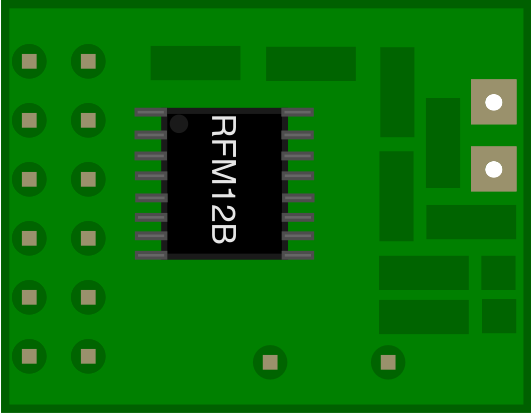
 Design with RFM12B Transceiver DIP Package in Cirkit Designer
Introduction
The RFM12B is a low-power, low-cost wireless transceiver module manufactured by HopeRF. It is designed for short-range communication in the 433 MHz, 868 MHz, and 915 MHz frequency bands. The module is highly versatile and supports both FSK (Frequency Shift Keying) and OOK (On-Off Keying) modulation schemes, making it suitable for a wide range of wireless applications.
Explore Projects Built with RFM12B Transceiver DIP Package
 Open Project in Cirkit Designer
 Open Project in Cirkit Designer
 Open Project in Cirkit Designer
 Open Project in Cirkit Designer
Explore Projects Built with RFM12B Transceiver DIP Package
Open Project in Cirkit DesignerOpen Project in Cirkit DesignerOpen Project in Cirkit DesignerOpen Project in Cirkit DesignerCommon Applications
- Remote control systems
- Wireless sensor networks
- Home automation
- Industrial monitoring
- Data logging and telemetry
The RFM12B is particularly popular in hobbyist and IoT projects due to its ease of use, low power consumption, and compatibility with microcontrollers like the Arduino.
Technical Specifications
Key Technical Details
| Parameter | Value |
|---|---|
| Frequency Range | 433 MHz, 868 MHz, 915 MHz |
| Modulation | FSK, OOK |
| Supply Voltage | 2.2V to 3.8V |
| Operating Current | 12 mA (typical, during transmission) |
| Sleep Current | < 1 µA |
| Data Rate | 0.6 kbps to 115.2 kbps |
| Output Power | -18 dBm to +13 dBm (programmable) |
| Sensitivity | -105 dBm (at 2.4 kbps, FSK) |
| Communication Interface | SPI |
| Operating Temperature | -40°C to +85°C |
| Dimensions | 16 mm x 16 mm x 3 mm |
Pin Configuration and Descriptions
The RFM12B module in the DIP package has 16 pins. Below is the pinout and description:
| Pin Number | Pin Name | Description |
|---|---|---|
| 1 | GND | Ground connection |
| 2 | VDD | Positive supply voltage (2.2V to 3.8V) |
| 3 | SDO | Serial Data Output (SPI interface) |
| 4 | SDI | Serial Data Input (SPI interface) |
| 5 | SCK | Serial Clock Input (SPI interface) |
| 6 | nSEL | Chip Select (active low) |
| 7 | nIRQ | Interrupt Request (active low, indicates data availability or status) |
| 8 | FSK/DATA | Data input/output for FSK or OOK modulation |
| 9 | GND | Ground connection |
| 10 | ANT | Antenna connection |
| 11 | GND | Ground connection |
| 12 | VDD | Positive supply voltage (2.2V to 3.8V) |
| 13 | CLK | Clock output (optional, can be used to drive external microcontroller) |
| 14 | nRES | Reset pin (active low, optional for manual reset) |
| 15 | GND | Ground connection |
| 16 | GND | Ground connection |
Usage Instructions
How to Use the RFM12B in a Circuit
- Power Supply: Connect the VDD pins to a regulated 3.3V power supply and the GND pins to ground.
- Antenna: Attach a suitable antenna to the ANT pin for optimal wireless performance. A simple wire antenna of 1/4 wavelength is often sufficient.
- SPI Interface: Connect the SPI pins (SDO, SDI, SCK, and nSEL) to the corresponding SPI pins on your microcontroller.
- Interrupt Handling: Connect the nIRQ pin to a GPIO pin on your microcontroller to handle interrupts for data availability or status changes.
- Data Communication: Use the FSK/DATA pin for transmitting or receiving data, depending on the mode of operation.
Important Considerations
- Voltage Levels: Ensure that the SPI signals are compatible with the RFM12B's voltage levels (3.3V logic). Use level shifters if interfacing with a 5V microcontroller.
- Antenna Design: The antenna length and placement significantly affect the module's range and performance. Use a 1/4 wavelength antenna for the selected frequency band.
- Decoupling Capacitors: Place a 0.1 µF ceramic capacitor close to the VDD pin to reduce noise and improve stability.
- Configuration: The RFM12B requires initialization via SPI commands to set the frequency, data rate, and other parameters.
Example Code for Arduino UNO
Below is an example of how to initialize and use the RFM12B module with an Arduino UNO:
#include <SPI.h>

// Define RFM12B pins
#define RFM12B_CS 10  // Chip Select pin
#define RFM12B_IRQ 2  // Interrupt pin

void setup() {
  // Initialize SPI
  SPI.begin();
  pinMode(RFM12B_CS, OUTPUT);
  pinMode(RFM12B_IRQ, INPUT);

  // Set Chip Select high (inactive)
  digitalWrite(RFM12B_CS, HIGH);

  // Initialize Serial Monitor
  Serial.begin(9600);
  Serial.println("Initializing RFM12B...");

  // Example: Send initialization commands to RFM12B
  digitalWrite(RFM12B_CS, LOW); // Select the RFM12B module
  SPI.transfer(0x80D7);         // Enable configuration settings
  SPI.transfer(0x82C8);         // Enable receiver and baseband
  SPI.transfer(0xA640);         // Set frequency to 433 MHz
  digitalWrite(RFM12B_CS, HIGH); // Deselect the module

  Serial.println("RFM12B Initialized.");
}

void loop() {
  // Example: Check for interrupt signal
  if (digitalRead(RFM12B_IRQ) == LOW) {
    Serial.println("Data available or status change detected.");
    // Add code to handle data reception or transmission
  }
}
Troubleshooting and FAQs
Common Issues and Solutions
No Communication with the Module
- Ensure the SPI connections are correct and secure.
- Verify that the microcontroller's SPI clock speed is compatible with the RFM12B.
- Check the power supply voltage (2.2V to 3.8V) and ensure it is stable.
Poor Wireless Range
- Use a properly tuned antenna for the selected frequency band.
- Avoid placing the module near metal objects or other sources of interference.
- Increase the output power setting via SPI commands.
Module Not Responding
- Verify that the nSEL pin is being toggled correctly during SPI communication.
- Check the nRES pin to ensure the module is not stuck in a reset state.
Data Corruption
- Ensure that the data rate and frequency settings match between the transmitter and receiver.
- Use error-checking mechanisms like CRC to detect and correct transmission errors.
FAQs
Q: Can the RFM12B operate at 5V?
A: No, the RFM12B operates at a maximum voltage of 3.8V. Use a voltage regulator or level shifters when interfacing with 5V systems.
Q: What is the maximum range of the RFM12B?
A: The range depends on the antenna design, output power, and environmental conditions. Typically, it can achieve up to 300 meters in open space.
Q: Is the RFM12B compatible with the Arduino?
A: Yes, the RFM12B can be easily interfaced with Arduino boards using the SPI interface.
Q: Can I use multiple RFM12B modules in the same network?
A: Yes, the RFM12B supports addressing and can be configured for multi-node communication.
This concludes the documentation for the RFM12B Transceiver DIP Package.