How to Use Battery Indicator with test button: Examples, Pinouts, and Specs
Introduction
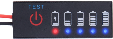
The Battery Indicator with Test Button is a compact and efficient device designed to display the charge level of a battery. It features a simple interface with an LED or bar graph display and a test button that allows users to check the battery's status on demand. This component is ideal for portable electronics, battery-powered tools, and DIY projects where monitoring battery health is essential.
Explore Projects Built with Battery Indicator with test button


Explore Projects Built with Battery Indicator with test button
Common Applications and Use Cases
- Portable electronic devices (e.g., flashlights, radios)
- Battery-powered tools and equipment
- DIY electronics and robotics projects
- Power banks and backup power systems
- Electric vehicles and scooters
Technical Specifications
Key Technical Details
- Operating Voltage: 3V to 24V (depending on the model)
- Current Consumption: Typically 10mA to 20mA during operation
- Display Type: LED bar graph or segmented display
- Test Button: Momentary push-button for status check
- Accuracy: ±5% (varies by model)
- Operating Temperature: -10°C to 60°C
- Dimensions: Varies by model, typically compact for easy integration
Pin Configuration and Descriptions
The Battery Indicator with Test Button typically has the following pin configuration:
| Pin Name | Description |
|---|---|
| VCC | Positive power supply input. Connect to the positive terminal of the battery. |
| GND | Ground connection. Connect to the negative terminal of the battery. |
| TEST | Input for the test button. Activates the display when pressed. |
| OUT | Optional output pin for interfacing with external circuits (if available). |
Usage Instructions
How to Use the Component in a Circuit
- Power Connection: Connect the
VCCpin to the positive terminal of the battery and theGNDpin to the negative terminal. - Test Button: Wire the
TESTpin to a momentary push-button switch. When the button is pressed, the battery's charge level will be displayed. - Display: The LED or bar graph display will light up to indicate the battery's charge level. The number of lit segments corresponds to the remaining charge.
- Optional Output: If the component includes an
OUTpin, it can be connected to an external circuit for additional functionality, such as triggering an alarm when the battery is low.
Important Considerations and Best Practices
- Voltage Compatibility: Ensure the battery's voltage is within the operating range of the indicator. Exceeding the voltage limit may damage the component.
- Button Debouncing: If the test button is connected to a microcontroller, consider implementing software or hardware debouncing to avoid false readings.
- Power Consumption: The indicator consumes a small amount of power. For long-term battery monitoring, disconnect the indicator when not in use to conserve energy.
- Mounting: Secure the indicator in a location where the display and test button are easily accessible.
Arduino UNO Example Code
The Battery Indicator with Test Button can be connected to an Arduino UNO for additional functionality, such as logging battery levels or triggering alerts. Below is an example code snippet:
// Define pin connections
const int testButtonPin = 2;  // Pin connected to the test button
const int batteryPin = A0;    // Analog pin connected to the battery voltage divider
const int ledPin = 13;        // Optional LED for low battery alert

void setup() {
  pinMode(testButtonPin, INPUT_PULLUP); // Set test button pin as input with pull-up
  pinMode(ledPin, OUTPUT);             // Set LED pin as output
  Serial.begin(9600);                  // Initialize serial communication
}

void loop() {
  // Check if the test button is pressed
  if (digitalRead(testButtonPin) == LOW) {
    delay(50); // Debounce delay
    if (digitalRead(testButtonPin) == LOW) {
      // Read battery voltage
      int batteryValue = analogRead(batteryPin);
      float batteryVoltage = (batteryValue / 1023.0) * 5.0; // Convert to voltage
      Serial.print("Battery Voltage: ");
      Serial.println(batteryVoltage);

      // Check for low battery
      if (batteryVoltage < 3.3) { // Example threshold for low battery
        digitalWrite(ledPin, HIGH); // Turn on LED
      } else {
        digitalWrite(ledPin, LOW);  // Turn off LED
      }
    }
  }
}
Troubleshooting and FAQs
Common Issues and Solutions
No Display When Button is Pressed:
- Cause: Incorrect wiring or insufficient battery voltage.
- Solution: Verify the connections to the
VCC,GND, andTESTpins. Ensure the battery voltage is within the operating range.
Inaccurate Battery Level Indication:
- Cause: Voltage divider or calibration issue.
- Solution: Check the voltage divider circuit (if used) and ensure proper calibration of the indicator.
Indicator Consumes Too Much Power:
- Cause: Indicator left connected continuously.
- Solution: Use the test button to activate the indicator only when needed. Disconnect the indicator during long-term storage.
Test Button Not Responding:
- Cause: Faulty button or poor connection.
- Solution: Test the button with a multimeter and ensure proper wiring to the
TESTpin.
FAQs
Q: Can this indicator be used with rechargeable batteries?
- A: Yes, it is compatible with most rechargeable batteries, as long as the voltage is within the operating range.
Q: How do I adjust the low battery threshold?
- A: If the indicator includes an adjustable threshold, refer to the manufacturer's instructions. For Arduino-based setups, modify the threshold in the code.
Q: Can I use this indicator with a 12V car battery?
- A: Yes, but ensure the indicator supports 12V operation. Use a voltage divider if necessary to step down the voltage.
Q: Is the test button required for operation?
- A: The test button is optional but recommended for on-demand status checks. The indicator can be wired for continuous display if desired.