
How to Use 4X4 Membrane Matrix Keypad: Examples, Pinouts, and Specs
 Design with 4X4 Membrane Matrix Keypad in Cirkit Designer
Introduction
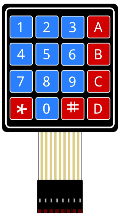
The 4X4 Membrane Matrix Keypad (Manufacturer: Parallax Inc., Part ID: 27899) is a compact and versatile input device designed for user interaction in electronic systems. It features 16 keys arranged in a 4x4 grid, making it ideal for applications requiring numeric or alphanumeric input. The keypad uses a thin, flexible membrane that registers key presses when the top layer contacts the bottom layer, sending signals to a microcontroller for processing.
Explore Projects Built with 4X4 Membrane Matrix Keypad
 Open Project in Cirkit Designer
 Open Project in Cirkit Designer
 Open Project in Cirkit Designer
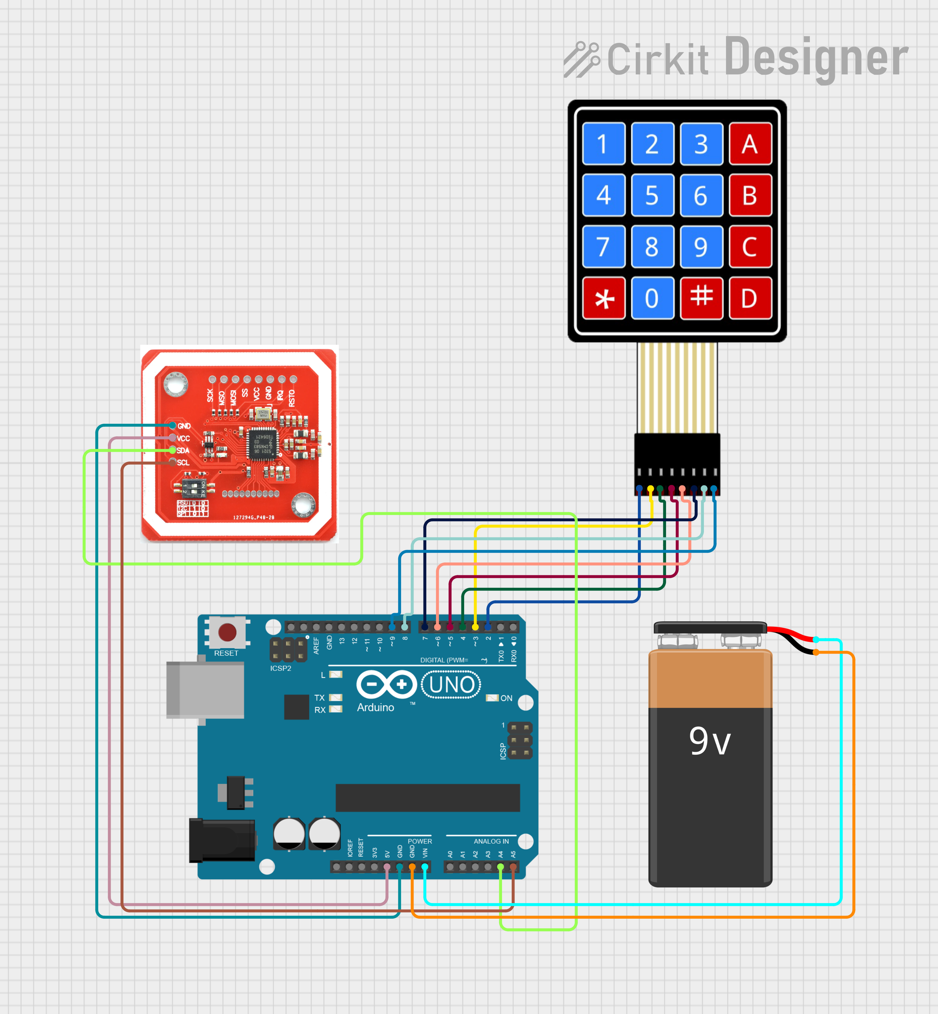 Open Project in Cirkit Designer
Explore Projects Built with 4X4 Membrane Matrix Keypad
Open Project in Cirkit DesignerOpen Project in Cirkit DesignerOpen Project in Cirkit DesignerOpen Project in Cirkit DesignerCommon Applications and Use Cases
- Security systems (e.g., PIN entry for locks)
- Home automation control panels
- Calculator-style input devices
- Menu navigation in embedded systems
- Robotics and IoT projects
Technical Specifications
The following table outlines the key technical details of the 4X4 Membrane Matrix Keypad:
| Parameter | Specification |
|---|---|
| Manufacturer | Parallax Inc. |
| Part ID | 27899 |
| Keypad Layout | 4 rows x 4 columns (16 keys total) |
| Operating Voltage | 3.3V to 5V |
| Maximum Current | 20 mA |
| Connector Type | 8-pin ribbon cable |
| Dimensions | 69 mm x 77 mm |
| Keypad Material | Flexible membrane |
| Operating Temperature | -20°C to 50°C |
Pin Configuration and Descriptions
The keypad has an 8-pin ribbon cable that connects to the rows and columns of the matrix. The pinout is as follows:
| Pin Number | Connection | Description |
|---|---|---|
| 1 | Row 1 | Connects to the first row of keys |
| 2 | Row 2 | Connects to the second row of keys |
| 3 | Row 3 | Connects to the third row of keys |
| 4 | Row 4 | Connects to the fourth row of keys |
| 5 | Column 1 | Connects to the first column of keys |
| 6 | Column 2 | Connects to the second column of keys |
| 7 | Column 3 | Connects to the third column of keys |
| 8 | Column 4 | Connects to the fourth column of keys |
Usage Instructions
How to Use the Component in a Circuit
Wiring the Keypad:
- Connect the 8-pin ribbon cable to your microcontroller or development board.
- Pins 1-4 correspond to the rows, and pins 5-8 correspond to the columns.
- Use pull-up or pull-down resistors if necessary to stabilize the signal.
Scanning the Keypad:
- The keypad operates on a matrix scanning principle. To detect a key press:
- Set one row pin HIGH and the others LOW.
- Check the column pins for a HIGH signal.
- Repeat this process for all rows to identify the pressed key.
- The keypad operates on a matrix scanning principle. To detect a key press:
Example Circuit:
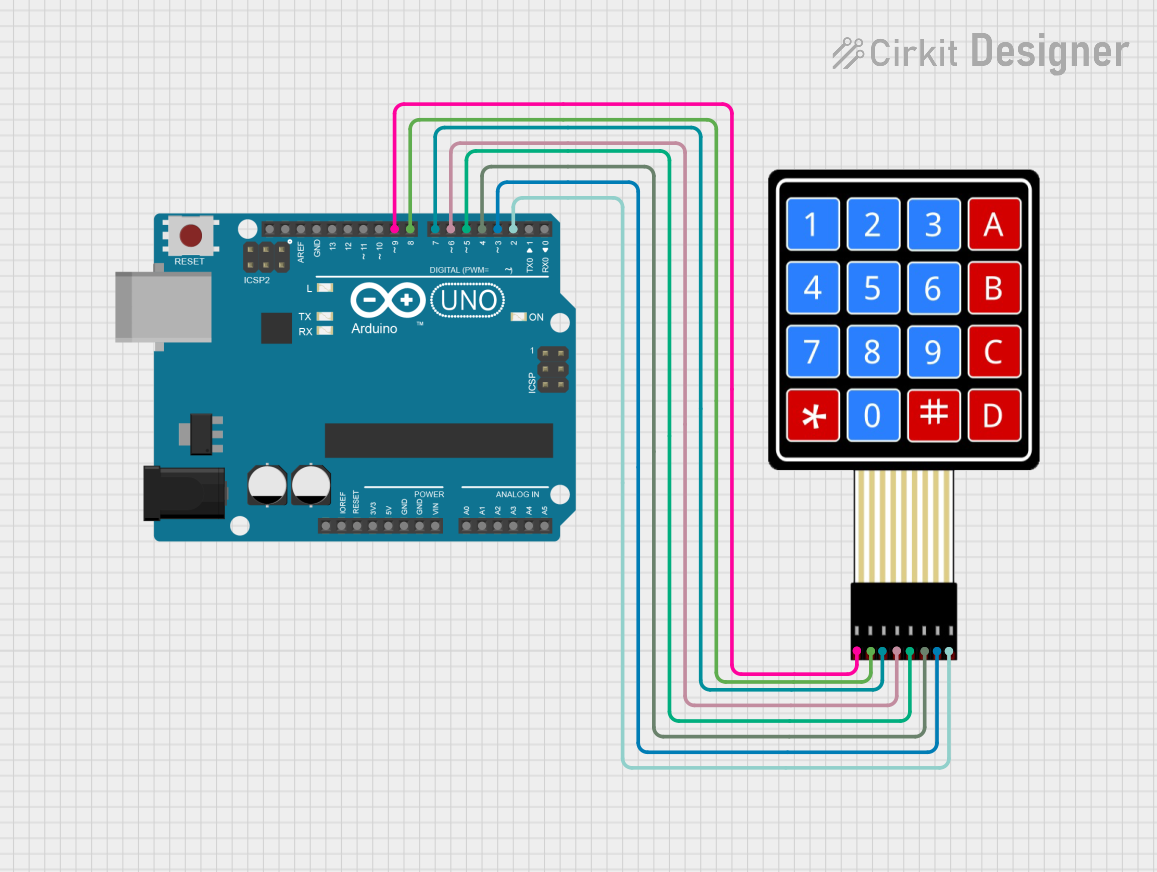
- Connect the keypad to an Arduino UNO as follows:
- Row pins (1-4) to Arduino digital pins 2, 3, 4, and 5.
- Column pins (5-8) to Arduino digital pins 6, 7, 8, and 9.
- Connect the keypad to an Arduino UNO as follows:
Important Considerations and Best Practices
- Debouncing: Key presses may generate noise or multiple signals. Use software debouncing techniques to ensure accurate key detection.
- Voltage Compatibility: Ensure the keypad's operating voltage matches your microcontroller's input voltage (3.3V or 5V).
- Avoid Excessive Force: The membrane is flexible but can be damaged by excessive pressure.
Arduino UNO Example Code
Below is an example code snippet for interfacing the 4X4 Membrane Matrix Keypad with an Arduino UNO:
#include <Keypad.h>

// Define the rows and columns of the keypad
const byte ROWS = 4; // Four rows
const byte COLS = 4; // Four columns

// Define the keymap for the keypad
char keys[ROWS][COLS] = {
  {'1', '2', '3', 'A'},
  {'4', '5', '6', 'B'},
  {'7', '8', '9', 'C'},
  {'*', '0', '#', 'D'}
};

// Define the row and column pins
byte rowPins[ROWS] = {2, 3, 4, 5}; // Connect to the row pins of the keypad
byte colPins[COLS] = {6, 7, 8, 9}; // Connect to the column pins of the keypad

// Create a Keypad object
Keypad keypad = Keypad(makeKeymap(keys), rowPins, colPins, ROWS, COLS);

void setup() {
  Serial.begin(9600); // Initialize serial communication
  Serial.println("4X4 Membrane Keypad Test");
}

void loop() {
  char key = keypad.getKey(); // Check for key press

  if (key) {
    // Print the pressed key to the Serial Monitor
    Serial.print("Key Pressed: ");
    Serial.println(key);
  }
}
Notes on the Code
- The
Keypadlibrary is used to simplify interfacing with the keypad. Install it via the Arduino Library Manager if not already installed. - The
keysarray defines the layout of the keypad, which can be customized as needed.
Troubleshooting and FAQs
Common Issues and Solutions
No Key Press Detected:
- Verify the wiring between the keypad and the microcontroller.
- Check for loose connections or damaged ribbon cables.
Incorrect Key Press Detected:
- Ensure the
keysarray in the code matches the physical layout of the keypad. - Check for cross-talk between rows and columns due to improper grounding.
- Ensure the
Multiple Key Presses Registered:
- Implement software debouncing to filter out noise.
- Verify that no conductive debris is shorting the keypad contacts.
Keypad Not Responding:
- Confirm that the operating voltage is within the specified range (3.3V to 5V).
- Test the keypad with a multimeter to ensure continuity between rows and columns.
FAQs
Q: Can I use this keypad with a Raspberry Pi?
A: Yes, the keypad can be used with a Raspberry Pi. Use GPIO pins and a Python library like pad4pi for interfacing.
Q: How durable is the membrane material?
A: The membrane is designed for light to moderate use. Avoid excessive force or exposure to harsh environments to prolong its lifespan.
Q: Can I customize the key labels?
A: Yes, you can overlay custom labels on the keypad, but ensure they do not interfere with key presses.
This concludes the documentation for the 4X4 Membrane Matrix Keypad.