How to Use SSR - 40da: Examples, Pinouts, and Specs
Introduction
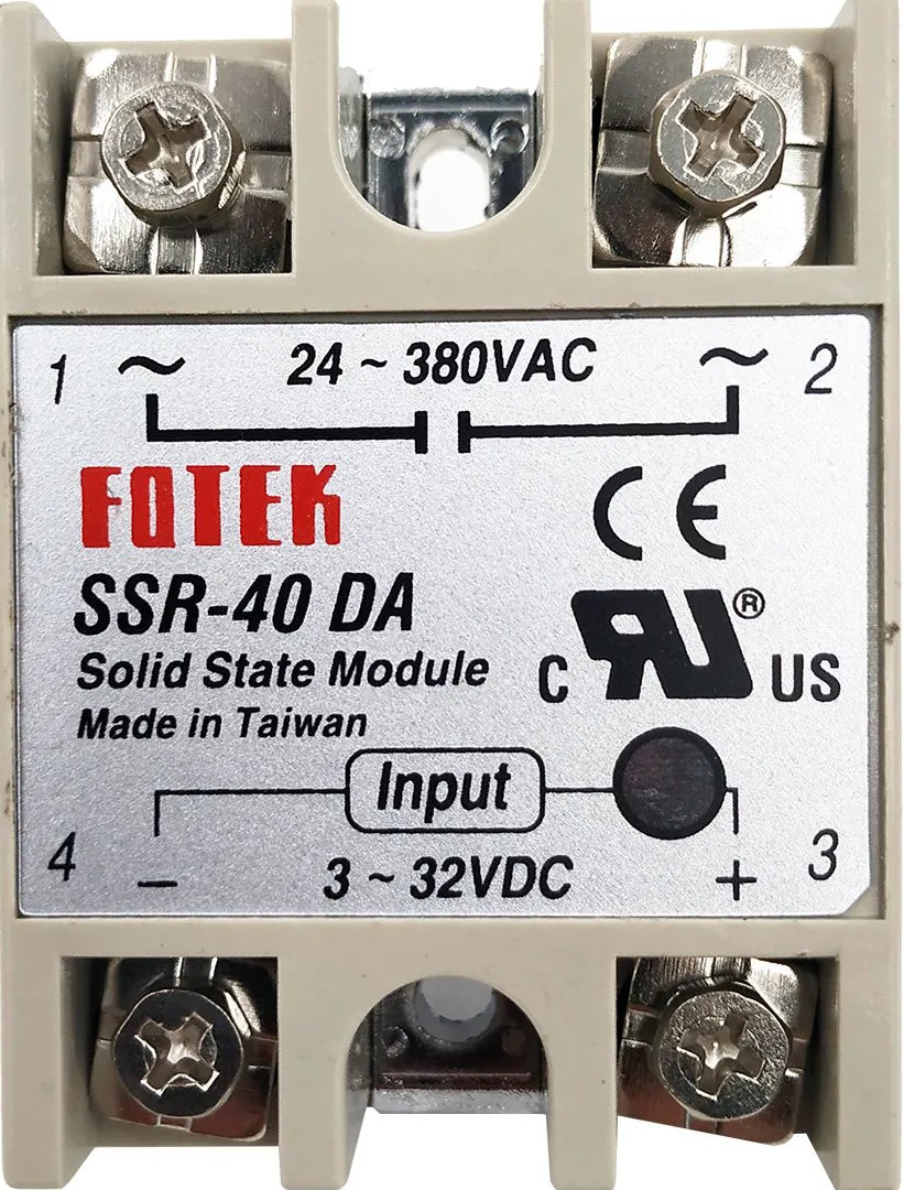
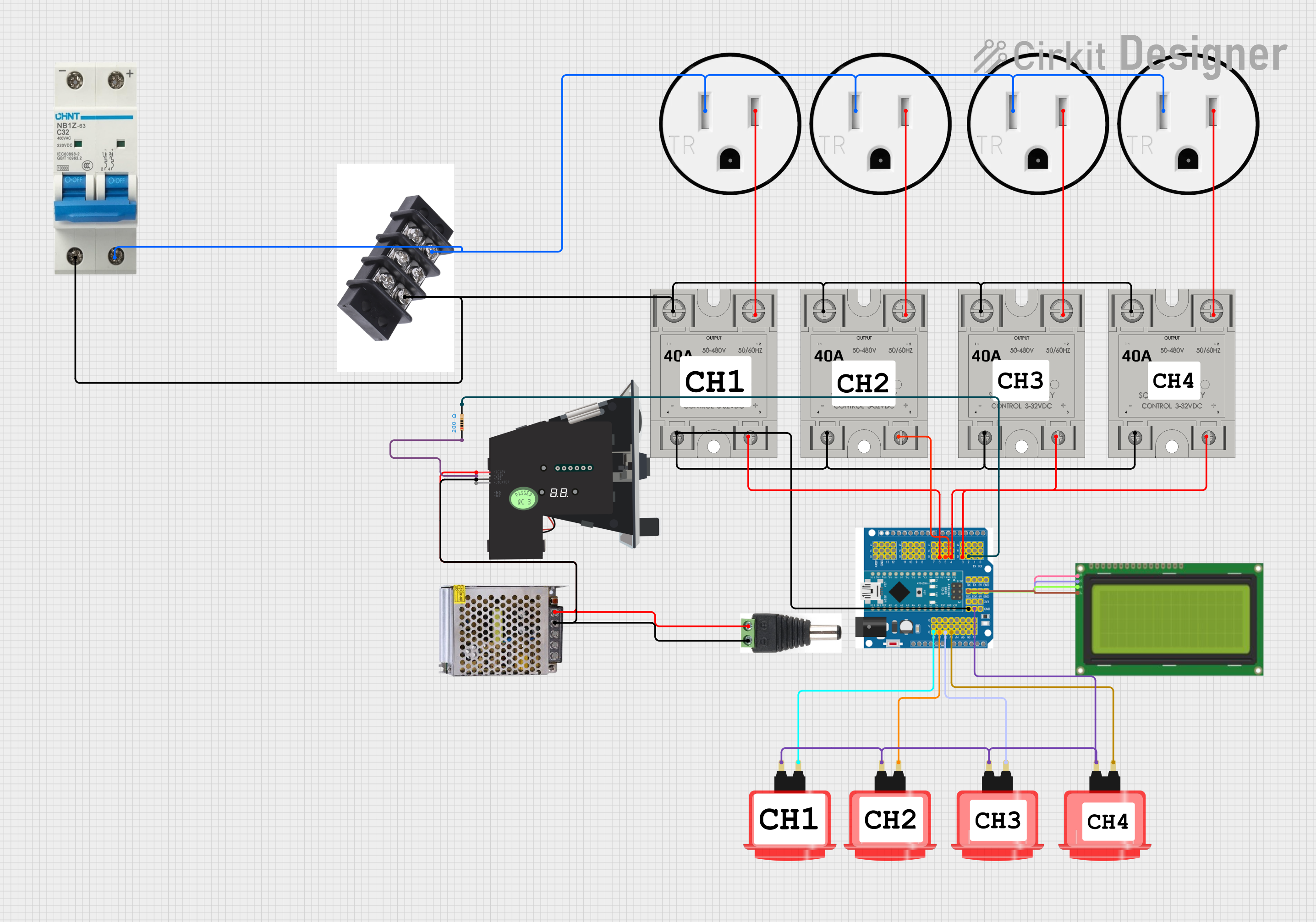
The SSR-40DA is a Solid State Relay (SSR) designed for high-performance switching applications. It is capable of handling loads up to 40 amps and operates without mechanical wear, making it highly reliable and durable. Unlike traditional electromechanical relays, the SSR-40DA uses semiconductor switching elements, enabling fast and silent operation. This component is widely used in industrial automation, heating systems, motor control, and other applications requiring efficient and reliable AC load switching.
Explore Projects Built with SSR - 40da


Explore Projects Built with SSR - 40da
Common Applications:
- Industrial automation and control systems
- Heating element control (e.g., ovens, furnaces)
- Motor speed control
- Lighting systems
- Home automation projects
Technical Specifications
Below are the key technical details of the SSR-40DA:
| Parameter | Value |
|---|---|
| Load Voltage Range | 24V AC to 380V AC |
| Load Current Rating | 40A |
| Control Voltage Range | 3V DC to 32V DC |
| Trigger Current | ≤7.5mA |
| On-State Voltage Drop | ≤1.6V |
| Off-State Leakage Current | ≤2mA |
| Isolation Voltage | ≥2500V AC |
| Operating Temperature | -30°C to +80°C |
| Mounting Type | Panel Mount |
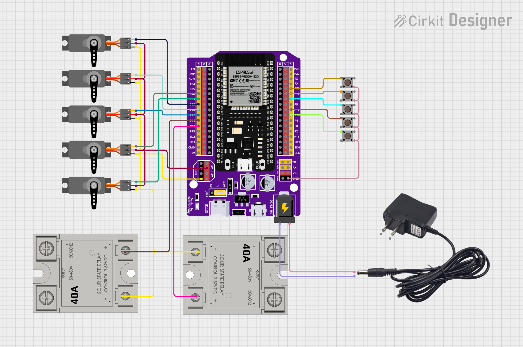
Pin Configuration and Descriptions
The SSR-40DA has four terminals, as described below:
| Pin | Label | Description |
|---|---|---|
| 1 | Input (+) | Positive control signal input (3V DC to 32V DC). Connect to the control circuit. |
| 2 | Input (-) | Negative control signal input (ground). |
| 3 | Load Terminal 1 | Connect to one side of the AC load. |
| 4 | Load Terminal 2 | Connect to the AC power source or the other side of the load. |
Usage Instructions
How to Use the SSR-40DA in a Circuit
Control Signal Connection:
- Connect the positive control signal (3V DC to 32V DC) to the
Input (+)terminal. - Connect the ground of the control signal to the
Input (-)terminal. - Ensure the control signal voltage is within the specified range to activate the relay.
- Connect the positive control signal (3V DC to 32V DC) to the
Load Connection:
- Connect one side of the AC load to
Load Terminal 1. - Connect the other side of the AC load to the AC power source through
Load Terminal 2.
- Connect one side of the AC load to
Mounting:
- Secure the SSR-40DA to a heat sink or metal surface to dissipate heat effectively, especially for high-current loads.
Power On:
- When the control signal is applied, the SSR will switch the AC load on.
- When the control signal is removed, the SSR will switch the AC load off.
Important Considerations and Best Practices
- Heat Dissipation: Use a heat sink or cooling fan to prevent overheating during high-current operation.
- Snubber Circuit: For inductive loads (e.g., motors), use a snubber circuit to protect the SSR from voltage spikes.
- Isolation: Ensure proper electrical isolation between the control and load sides to prevent damage to the control circuit.
- Polarity: Observe correct polarity for the control signal to avoid malfunction.
Example: Using SSR-40DA with Arduino UNO
Below is an example of how to control the SSR-40DA using an Arduino UNO to switch an AC load.
// Example: Controlling SSR-40DA with Arduino UNO
// This code toggles the SSR on and off every 2 seconds.

const int ssrPin = 7; // Pin connected to the SSR control input

void setup() {
  pinMode(ssrPin, OUTPUT); // Set the SSR pin as an output
}

void loop() {
  digitalWrite(ssrPin, HIGH); // Turn the SSR on (AC load ON)
  delay(2000);                // Wait for 2 seconds
  digitalWrite(ssrPin, LOW);  // Turn the SSR off (AC load OFF)
  delay(2000);                // Wait for 2 seconds
}
Note: Ensure the Arduino's ground is connected to the SSR's Input (-) terminal.
Troubleshooting and FAQs
Common Issues and Solutions
SSR Does Not Switch the Load:
- Verify that the control signal voltage is within the specified range (3V DC to 32V DC).
- Check the polarity of the control signal connections.
- Ensure the load current does not exceed 40A.
Excessive Heating:
- Ensure the SSR is mounted on a heat sink or metal surface for proper heat dissipation.
- Check for loose connections or overloaded circuits.
Load Flickering:
- Verify that the control signal is stable and not fluctuating.
- For inductive loads, use a snubber circuit to suppress voltage spikes.
Leakage Current When Off:
- A small leakage current (≤2mA) is normal for SSRs. Ensure the load can tolerate this.
FAQs
Q1: Can the SSR-40DA switch DC loads?
A1: No, the SSR-40DA is designed for AC loads only. For DC loads, use a DC-specific SSR.
Q2: What happens if the load exceeds 40A?
A2: Exceeding the rated current can damage the SSR. Use a relay with a higher current rating or reduce the load.
Q3: Can I use the SSR-40DA without a heat sink?
A3: For low-current applications, a heat sink may not be necessary. However, for high-current loads, a heat sink is essential to prevent overheating.
Q4: Is the SSR-40DA suitable for switching high-frequency signals?
A4: No, SSRs are not designed for high-frequency switching. Use a transistor or MOSFET for such applications.