Cirkit Designer Logo
Cirkit Designer
Your all-in-one circuit design IDE
Home / 
Component Documentation

How to Use T-A7670G R2: Examples, Pinouts, and Specs

Image of T-A7670G R2
Cirkit Designer LogoDesign with T-A7670G R2 in Cirkit Designer

Introduction

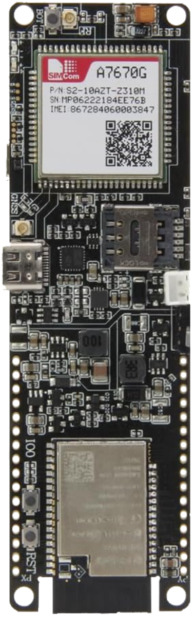
The T-A7670G R2, manufactured by LILYGO, is a low-dropout (LDO) voltage regulator designed to deliver a stable and reliable output voltage with minimal input-to-output voltage differential. This component is ideal for applications requiring precise voltage regulation, such as powering microcontrollers, sensors, and other sensitive electronic components. Its compact design and high efficiency make it suitable for portable devices, embedded systems, and battery-powered applications.

Explore Projects Built with T-A7670G R2

Use Cirkit Designer to design, explore, and prototype these projects online. Some projects support real-time simulation. Click "Open Project" to start designing instantly!
Satellite-Based Timing and Navigation System with SDR and Atomic Clock Synchronization
Image of GPS 시스템 측정 구성도_Confirm: A project utilizing T-A7670G R2 in a practical application
This circuit appears to be a complex system involving power supply management, GPS and timing synchronization, and data communication. It includes a SI-TEX G1 Satellite Compass for GPS data, an XHTF1021 Atomic Rubidium Clock for precise timing, and Ettus USRP B200 units for software-defined radio communication. Power is supplied through various SMPS units and distributed via terminal blocks and DC jacks. Data communication is facilitated by Beelink MINI S12 N95 computers, RS232 splitters, and a 1000BASE-T Media Converter for network connectivity. RF Directional Couplers are used to interface antennas with the USRP units, and the entire system is likely contained within cases for protection and organization.
Cirkit Designer LogoOpen Project in Cirkit Designer
Lilygo 7670e-Based Smart Interface with LCD Display and Keypad
Image of Paower: A project utilizing T-A7670G R2 in a practical application
This circuit features a Lilygo 7670e microcontroller interfaced with a 16x2 I2C LCD for display, a 4X4 membrane matrix keypad for input, and an arcade button for additional control. It also includes a 4G antenna and a GPS antenna for communication and location tracking capabilities.
Cirkit Designer LogoOpen Project in Cirkit Designer
Battery-Powered Emergency Alert System with NUCLEO-F072RB, SIM800L, and GPS NEO 6M
Image of women safety: A project utilizing T-A7670G R2 in a practical application
This circuit is an emergency alert system that uses a NUCLEO-F072RB microcontroller to send SMS alerts and make calls via a SIM800L GSM module, while obtaining location data from a GPS NEO 6M module. The system is powered by a Li-ion battery and includes a TP4056 module for battery charging and protection, with a rocker switch to control power to the microcontroller.
Cirkit Designer LogoOpen Project in Cirkit Designer
Satellite Compass and Network-Integrated GPS Data Processing System
Image of GPS 시스템 측정 구성도_241016: A project utilizing T-A7670G R2 in a practical application
This circuit comprises a satellite compass, a mini PC, two GPS antennas, power supplies, a network switch, media converters, and an atomic rubidium clock. The satellite compass is powered by a triple output DC power supply and interfaces with an RS232 splitter for 1PPS signals. The mini PCs are connected to the USRP B200 devices via USB for data and power, and to media converters via Ethernet, which in turn connect to a network switch using fiber optic links. The antennas are connected to the USRP B200s through RF directional couplers, and the atomic clock provides a 1PPS input to the RS232 splitter.
Cirkit Designer LogoOpen Project in Cirkit Designer

Explore Projects Built with T-A7670G R2

Use Cirkit Designer to design, explore, and prototype these projects online. Some projects support real-time simulation. Click "Open Project" to start designing instantly!
Image of GPS 시스템 측정 구성도_Confirm: A project utilizing T-A7670G R2 in a practical application
Satellite-Based Timing and Navigation System with SDR and Atomic Clock Synchronization
This circuit appears to be a complex system involving power supply management, GPS and timing synchronization, and data communication. It includes a SI-TEX G1 Satellite Compass for GPS data, an XHTF1021 Atomic Rubidium Clock for precise timing, and Ettus USRP B200 units for software-defined radio communication. Power is supplied through various SMPS units and distributed via terminal blocks and DC jacks. Data communication is facilitated by Beelink MINI S12 N95 computers, RS232 splitters, and a 1000BASE-T Media Converter for network connectivity. RF Directional Couplers are used to interface antennas with the USRP units, and the entire system is likely contained within cases for protection and organization.
Cirkit Designer LogoOpen Project in Cirkit Designer
Image of Paower: A project utilizing T-A7670G R2 in a practical application
Lilygo 7670e-Based Smart Interface with LCD Display and Keypad
This circuit features a Lilygo 7670e microcontroller interfaced with a 16x2 I2C LCD for display, a 4X4 membrane matrix keypad for input, and an arcade button for additional control. It also includes a 4G antenna and a GPS antenna for communication and location tracking capabilities.
Cirkit Designer LogoOpen Project in Cirkit Designer
Image of women safety: A project utilizing T-A7670G R2 in a practical application
Battery-Powered Emergency Alert System with NUCLEO-F072RB, SIM800L, and GPS NEO 6M
This circuit is an emergency alert system that uses a NUCLEO-F072RB microcontroller to send SMS alerts and make calls via a SIM800L GSM module, while obtaining location data from a GPS NEO 6M module. The system is powered by a Li-ion battery and includes a TP4056 module for battery charging and protection, with a rocker switch to control power to the microcontroller.
Cirkit Designer LogoOpen Project in Cirkit Designer
Image of GPS 시스템 측정 구성도_241016: A project utilizing T-A7670G R2 in a practical application
Satellite Compass and Network-Integrated GPS Data Processing System
This circuit comprises a satellite compass, a mini PC, two GPS antennas, power supplies, a network switch, media converters, and an atomic rubidium clock. The satellite compass is powered by a triple output DC power supply and interfaces with an RS232 splitter for 1PPS signals. The mini PCs are connected to the USRP B200 devices via USB for data and power, and to media converters via Ethernet, which in turn connect to a network switch using fiber optic links. The antennas are connected to the USRP B200s through RF directional couplers, and the atomic clock provides a 1PPS input to the RS232 splitter.
Cirkit Designer LogoOpen Project in Cirkit Designer

Common Applications

  • Powering microcontrollers (e.g., Arduino, ESP32)
  • Voltage regulation for sensors and analog circuits
  • Battery-powered devices
  • Portable electronics
  • Embedded systems requiring stable voltage levels

Technical Specifications

Key Technical Details

Parameter Value
Manufacturer Part ID T-A7670G R2
Input Voltage Range 2.5V to 6.0V
Output Voltage Options 1.8V, 3.3V, 5.0V (fixed)
Maximum Output Current 500 mA
Dropout Voltage 200 mV (typical at 500 mA)
Quiescent Current 50 µA (typical)
Operating Temperature -40°C to +85°C
Package Type SOT-23-5

Pin Configuration and Descriptions

The T-A7670G R2 is typically available in a SOT-23-5 package with the following pinout:

Pin Number Pin Name Description
1 VIN Input voltage (connect to power source)
2 GND Ground (connect to circuit ground)
3 EN Enable pin (active high, connect to logic HIGH
to enable the regulator)
4 VOUT Regulated output voltage
5 NC No connection (leave unconnected or grounded)

Usage Instructions

How to Use the T-A7670G R2 in a Circuit

  1. Input Voltage: Connect the input voltage (VIN) to a power source within the range of 2.5V to 6.0V. Ensure the input voltage is at least 200 mV higher than the desired output voltage for proper regulation.
  2. Output Voltage: Connect the VOUT pin to the load requiring the regulated voltage. Use a decoupling capacitor (e.g., 1 µF to 10 µF) close to the VOUT pin to stabilize the output.
  3. Enable Pin: The EN pin must be pulled HIGH to enable the regulator. If unused, connect it to VIN.
  4. Ground: Connect the GND pin to the circuit ground.
  5. Bypass Capacitors: Place a capacitor (e.g., 1 µF ceramic) between VIN and GND to filter input noise.

Important Considerations

  • Thermal Management: Ensure adequate heat dissipation if the regulator operates near its maximum current rating.
  • Capacitor Selection: Use low-ESR capacitors for optimal performance.
  • Enable Pin Logic: If the EN pin is left floating, the regulator may not function correctly. Always tie it to a defined logic level.

Example: Using T-A7670G R2 with Arduino UNO

The T-A7670G R2 can be used to power an Arduino UNO with a stable 5V supply. Below is an example circuit and Arduino code to toggle the EN pin.

Circuit Diagram

  1. Connect a 6V power source to the VIN pin of the T-A7670G R2.
  2. Connect the VOUT pin to the 5V pin of the Arduino UNO.
  3. Connect the EN pin to a digital output pin (e.g., D7) of the Arduino UNO.
  4. Connect the GND pin to the Arduino's GND.

Arduino Code

// Example code to toggle the EN pin of the T-A7670G R2
const int enablePin = 7; // Pin connected to the EN pin of the regulator

void setup() {
  pinMode(enablePin, OUTPUT); // Set the enable pin as an output
  digitalWrite(enablePin, HIGH); // Enable the regulator
  delay(1000); // Wait for 1 second
}

void loop() {
  digitalWrite(enablePin, LOW); // Disable the regulator
  delay(2000); // Wait for 2 seconds
  digitalWrite(enablePin, HIGH); // Enable the regulator
  delay(2000); // Wait for 2 seconds
}

Troubleshooting and FAQs

Common Issues and Solutions

  1. No Output Voltage

    • Cause: EN pin is not connected or is LOW.
    • Solution: Ensure the EN pin is pulled HIGH or connected to VIN.
  2. Output Voltage Instability

    • Cause: Insufficient decoupling capacitors.
    • Solution: Add a 1 µF to 10 µF capacitor close to the VOUT pin.
  3. Excessive Heat

    • Cause: High current draw or insufficient heat dissipation.
    • Solution: Reduce the load current or improve thermal management (e.g., use a heatsink).
  4. Dropout Voltage Too High

    • Cause: Input voltage is too close to the output voltage.
    • Solution: Increase the input voltage to maintain at least 200 mV above the output voltage.

FAQs

Q1: Can the T-A7670G R2 output voltage be adjusted?
A1: No, the T-A7670G R2 provides fixed output voltage options (1.8V, 3.3V, or 5.0V). Select the appropriate version for your application.

Q2: What happens if the EN pin is left floating?
A2: The regulator may not operate correctly. Always connect the EN pin to a defined logic level (HIGH to enable, LOW to disable).

Q3: Can I use the T-A7670G R2 with a battery?
A3: Yes, the T-A7670G R2 is suitable for battery-powered applications, provided the input voltage is within the specified range.

Q4: What type of capacitors should I use?
A4: Use low-ESR ceramic capacitors for both input and output decoupling to ensure stable operation.


This concludes the documentation for the T-A7670G R2. For further assistance, refer to the manufacturer's datasheet or contact LILYGO support.