Cirkit Designer Logo
Cirkit Designer
Your all-in-one circuit design IDE
Home / 
Component Documentation

How to Use AO3400A mark A09T N Channel 30V 5.7A SMD MOSFET Transistor: Examples, Pinouts, and Specs

Image of AO3400A mark A09T N Channel 30V 5.7A SMD MOSFET Transistor
Cirkit Designer LogoDesign with AO3400A mark A09T N Channel 30V 5.7A SMD MOSFET Transistor in Cirkit Designer

Introduction

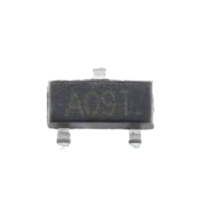
The AO3400A (marked as A09T) is a surface-mount N-channel MOSFET transistor designed for high-efficiency switching and amplification in electronic circuits. With a maximum voltage rating of 30V and a current handling capacity of up to 5.7A, this component is ideal for low-power DC-DC converters, motor drivers, and general-purpose switching applications. Its compact SOT-23 package makes it suitable for space-constrained designs.

Explore Projects Built with AO3400A mark A09T N Channel 30V 5.7A SMD MOSFET Transistor

Use Cirkit Designer to design, explore, and prototype these projects online. Some projects support real-time simulation. Click "Open Project" to start designing instantly!
STM32 Nucleo-Controlled Solenoid Actuation System
Image of stm32 braile: A project utilizing AO3400A mark A09T N Channel 30V 5.7A SMD MOSFET Transistor in a practical application
This circuit appears to be a microcontroller-driven array of push-pull solenoids with flyback diodes for protection. The STM32 Nucleo F303RE microcontroller's GPIO pins are connected to the gates of several nMOS transistors, which act as switches to control the current flow to the solenoids. A pushbutton with a pull-up resistor is also interfaced with the microcontroller for user input, and the power supply is connected to the solenoids with ground return paths through the nMOS transistors.
Cirkit Designer LogoOpen Project in Cirkit Designer
Battery-Powered Boost Converter with USB Type-C and BMS
Image of Weird Case: A project utilizing AO3400A mark A09T N Channel 30V 5.7A SMD MOSFET Transistor in a practical application
This circuit is a power management and conversion system that includes a boost converter, battery management system (BMS), and various MOSFETs and passive components. It is designed to regulate and boost the voltage from a 2000mAh battery, providing stable power output through a USB Type C interface. The circuit also includes protection and switching mechanisms to ensure safe and efficient power delivery.
Cirkit Designer LogoOpen Project in Cirkit Designer
Arduino UNO Controlled nMOS Transistor Array with Resistor Network
Image of elka_1: A project utilizing AO3400A mark A09T N Channel 30V 5.7A SMD MOSFET Transistor in a practical application
This circuit uses an Arduino UNO to control three nMOS transistors via three 1k Ohm resistors connected to digital pins D3, D6, and D9. The transistors' sources are tied to ground, and their gates are driven by the Arduino to switch the transistors on and off, likely for controlling high-power loads or other devices.
Cirkit Designer LogoOpen Project in Cirkit Designer
Transistor-Based Signal Modulation Circuit with AC/DC Power Integration
Image of PPPPP: A project utilizing AO3400A mark A09T N Channel 30V 5.7A SMD MOSFET Transistor in a practical application
This circuit appears to be a transistor-based switching or amplification system powered by a 12v battery, with an AC supply possibly for signal input or additional power. It includes filtering through ceramic capacitors and uses resistors for biasing the transistors. The presence of both PNP and NPN transistors suggests a push-pull configuration or a form of signal modulation.
Cirkit Designer LogoOpen Project in Cirkit Designer

Explore Projects Built with AO3400A mark A09T N Channel 30V 5.7A SMD MOSFET Transistor

Use Cirkit Designer to design, explore, and prototype these projects online. Some projects support real-time simulation. Click "Open Project" to start designing instantly!
Image of stm32 braile: A project utilizing AO3400A mark A09T N Channel 30V 5.7A SMD MOSFET Transistor in a practical application
STM32 Nucleo-Controlled Solenoid Actuation System
This circuit appears to be a microcontroller-driven array of push-pull solenoids with flyback diodes for protection. The STM32 Nucleo F303RE microcontroller's GPIO pins are connected to the gates of several nMOS transistors, which act as switches to control the current flow to the solenoids. A pushbutton with a pull-up resistor is also interfaced with the microcontroller for user input, and the power supply is connected to the solenoids with ground return paths through the nMOS transistors.
Cirkit Designer LogoOpen Project in Cirkit Designer
Image of Weird Case: A project utilizing AO3400A mark A09T N Channel 30V 5.7A SMD MOSFET Transistor in a practical application
Battery-Powered Boost Converter with USB Type-C and BMS
This circuit is a power management and conversion system that includes a boost converter, battery management system (BMS), and various MOSFETs and passive components. It is designed to regulate and boost the voltage from a 2000mAh battery, providing stable power output through a USB Type C interface. The circuit also includes protection and switching mechanisms to ensure safe and efficient power delivery.
Cirkit Designer LogoOpen Project in Cirkit Designer
Image of elka_1: A project utilizing AO3400A mark A09T N Channel 30V 5.7A SMD MOSFET Transistor in a practical application
Arduino UNO Controlled nMOS Transistor Array with Resistor Network
This circuit uses an Arduino UNO to control three nMOS transistors via three 1k Ohm resistors connected to digital pins D3, D6, and D9. The transistors' sources are tied to ground, and their gates are driven by the Arduino to switch the transistors on and off, likely for controlling high-power loads or other devices.
Cirkit Designer LogoOpen Project in Cirkit Designer
Image of PPPPP: A project utilizing AO3400A mark A09T N Channel 30V 5.7A SMD MOSFET Transistor in a practical application
Transistor-Based Signal Modulation Circuit with AC/DC Power Integration
This circuit appears to be a transistor-based switching or amplification system powered by a 12v battery, with an AC supply possibly for signal input or additional power. It includes filtering through ceramic capacitors and uses resistors for biasing the transistors. The presence of both PNP and NPN transistors suggests a push-pull configuration or a form of signal modulation.
Cirkit Designer LogoOpen Project in Cirkit Designer

Common Applications

  • DC-DC converters
  • Motor control circuits
  • Load switching in battery-powered devices
  • Signal amplification in low-power circuits
  • LED drivers

Technical Specifications

Key Specifications

Parameter Value
Type N-Channel MOSFET
Maximum Drain-Source Voltage (VDS) 30V
Maximum Gate-Source Voltage (VGS) ±20V
Continuous Drain Current (ID) 5.7A (at 25°C)
Pulsed Drain Current (IDM) 20A
Power Dissipation (PD) 1.4W (at 25°C)
RDS(on) (Drain-Source On Resistance) 13.5mΩ (at VGS = 10V)
Gate Threshold Voltage (VGS(th)) 1.0V - 2.5V
Operating Temperature Range -55°C to +150°C
Package SOT-23

Pin Configuration

The AO3400A is housed in a 3-pin SOT-23 package. The pinout is as follows:

Pin Number Pin Name Description
1 Gate Controls the MOSFET switching
2 Source Connected to the negative side of the circuit
3 Drain Connected to the load or positive side of the circuit

Usage Instructions

How to Use the AO3400A in a Circuit

  1. Gate Control: Apply a voltage to the Gate (Pin 1) to control the MOSFET. A voltage above the Gate Threshold Voltage (VGS(th)) will turn the MOSFET on, allowing current to flow between the Drain (Pin 3) and Source (Pin 2).
  2. Load Connection: Connect the load between the Drain (Pin 3) and the positive supply voltage. The Source (Pin 2) should be connected to ground.
  3. Gate Resistor: Use a resistor (typically 10Ω to 100Ω) in series with the Gate to limit inrush current and protect the MOSFET.
  4. Flyback Diode: For inductive loads (e.g., motors or relays), add a flyback diode across the load to protect the MOSFET from voltage spikes.

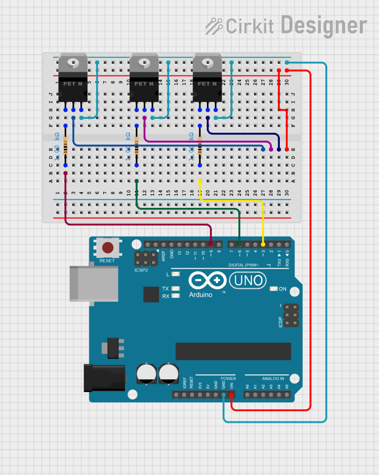
Example Circuit with Arduino UNO

The AO3400A can be used to control a 12V LED strip with an Arduino UNO. Below is an example circuit and code:

Circuit Connections

  • Drain (Pin 3): Connect to the negative terminal of the LED strip.
  • Source (Pin 2): Connect to ground.
  • Gate (Pin 1): Connect to an Arduino digital pin (e.g., D9) through a 100Ω resistor.
  • LED Strip Positive Terminal: Connect to a 12V power supply.

Arduino Code

// Define the MOSFET Gate pin
const int mosfetGatePin = 9;

void setup() {
  // Set the MOSFET Gate pin as an output
  pinMode(mosfetGatePin, OUTPUT);
}

void loop() {
  // Turn the LED strip ON
  digitalWrite(mosfetGatePin, HIGH);
  delay(1000); // Keep it ON for 1 second

  // Turn the LED strip OFF
  digitalWrite(mosfetGatePin, LOW);
  delay(1000); // Keep it OFF for 1 second
}

Important Considerations

  • Ensure the Gate voltage (VGS) does not exceed ±20V to avoid damaging the MOSFET.
  • Use proper heat dissipation techniques (e.g., PCB copper pads) if operating near the maximum current rating.
  • For high-speed switching, consider using a dedicated MOSFET driver to ensure fast and efficient Gate charging/discharging.

Troubleshooting and FAQs

Common Issues

  1. MOSFET Not Turning On

    • Cause: Insufficient Gate voltage.
    • Solution: Ensure the Gate voltage exceeds the Gate Threshold Voltage (VGS(th)) of 1.0V to 2.5V. For full conduction, apply at least 10V to the Gate.
  2. Excessive Heat Generation

    • Cause: High RDS(on) or insufficient heat dissipation.
    • Solution: Verify that the Gate voltage is high enough to minimize RDS(on). Use proper PCB design for heat dissipation.
  3. MOSFET Fails or Shorts

    • Cause: Voltage spikes from inductive loads or exceeding voltage/current ratings.
    • Solution: Add a flyback diode for inductive loads and ensure the voltage/current ratings are not exceeded.

FAQs

Q: Can the AO3400A be used for PWM control?
A: Yes, the AO3400A is suitable for PWM control due to its low RDS(on) and fast switching characteristics.

Q: What is the maximum Gate current?
A: The Gate current is typically very low, but it is recommended to use a resistor (10Ω to 100Ω) in series with the Gate to limit inrush current during switching.

Q: Can I use the AO3400A with a 3.3V microcontroller?
A: Yes, the AO3400A can be driven by a 3.3V microcontroller, as its Gate Threshold Voltage (VGS(th)) is as low as 1.0V. However, ensure the load current and RDS(on) are within acceptable limits at this Gate voltage.