The TLV9001 is a low-power, high-speed operational amplifier (op-amp) manufactured by Texas Instruments. It is designed for precision applications requiring high performance and efficiency. With its wide bandwidth, low offset voltage, and low noise characteristics, the TLV9001 is ideal for signal conditioning, amplification, and other analog signal processing tasks.
Explore Projects Built with TLV9001
Use Cirkit Designer to design, explore, and prototype these projects online. Some projects support real-time simulation. Click "Open Project" to start designing instantly!
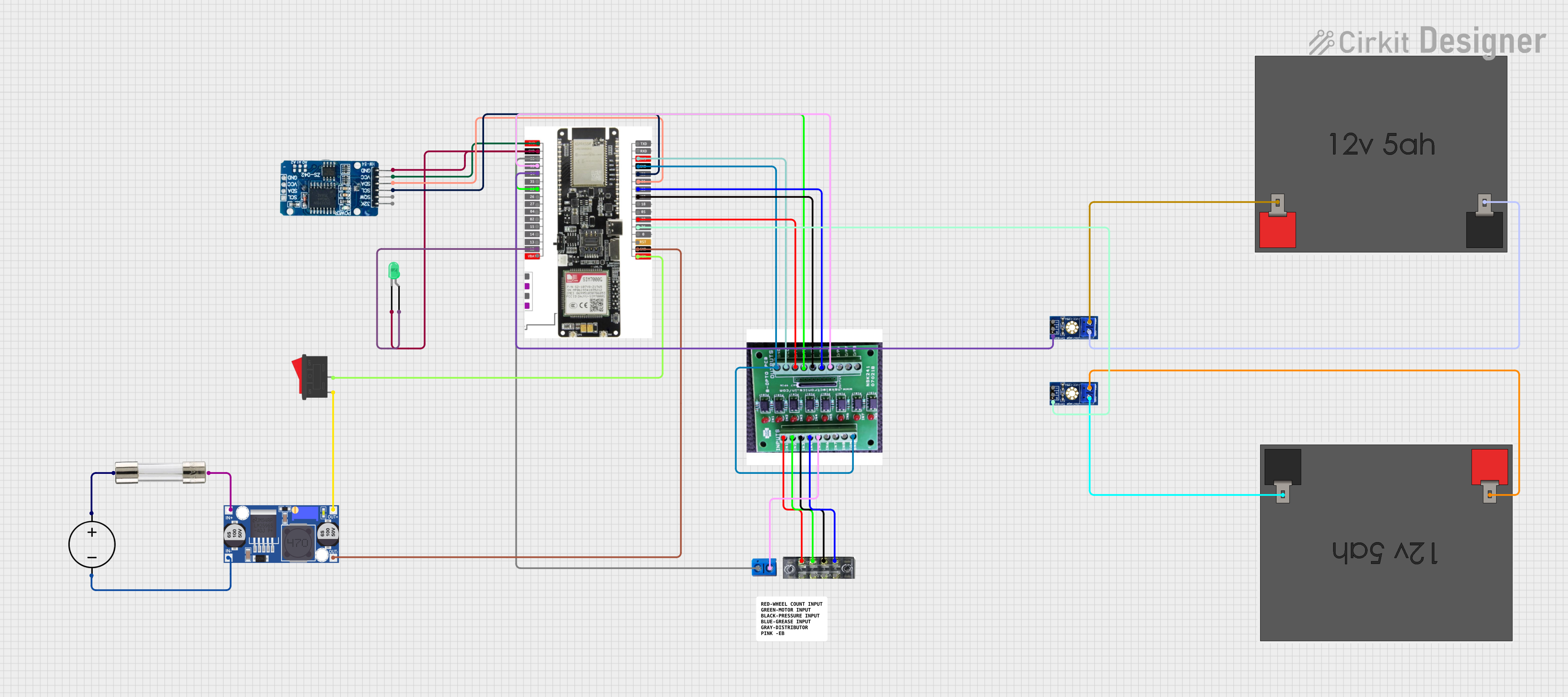
This circuit features a LilyGo-SIM7000G module for cellular communication and GPS functionality, interfaced with an RTC DS3231 for real-time clock capabilities. It includes voltage sensing through two voltage sensor modules, and uses an 8-channel opto-coupler for isolating different parts of the circuit. Power management is handled by a buck converter connected to a DC power source and batteries, with a fuse for protection and a rocker switch for on/off control. Additionally, there's an LED for indication purposes.
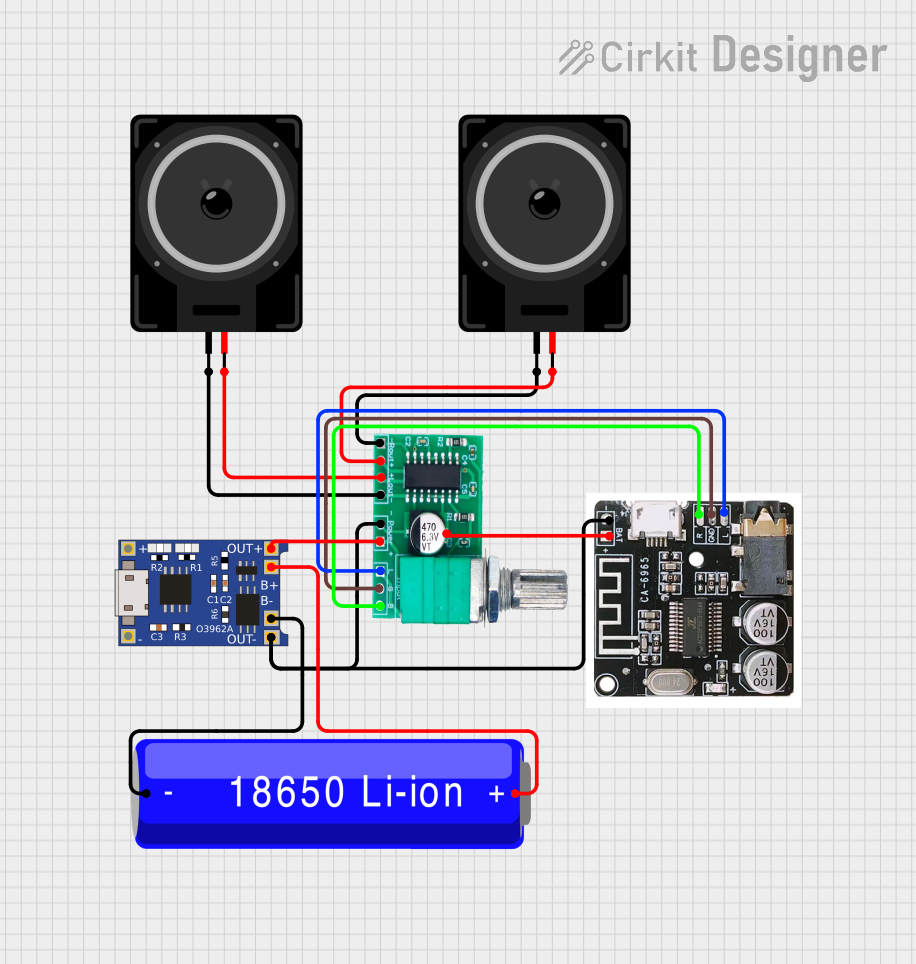
This circuit is a Bluetooth-enabled audio system powered by a rechargeable 18650 Li-ion battery. It includes a TP4056 module for battery charging and protection, a PAM8403 amplifier with volume control to drive two loudspeakers, and a Bluetooth audio receiver to wirelessly receive audio signals.
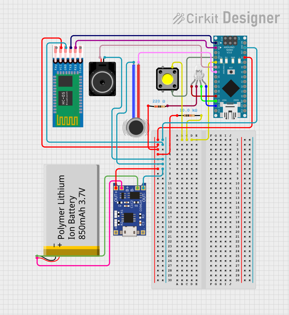
This is a portable, microcontroller-driven interactive device featuring Bluetooth connectivity, visual (RGB LED), auditory (loudspeaker), and haptic (vibration motor) feedback, user input (pushbutton), and a rechargeable power system (TP4056 with Li-ion battery).
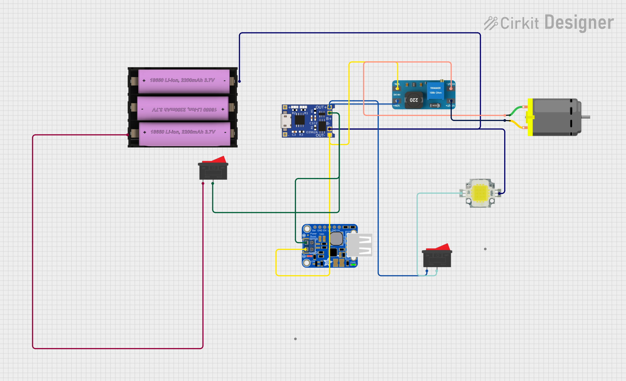
This circuit is designed to charge a Li-ion battery and power a DC motor and a 12V LED. The TP4056 module manages the battery charging process, while the PowerBoost 1000 and MT3608 boost converters step up the voltage to drive the motor and LED, respectively. Two rocker switches control the power flow to the LED and the charging circuit.
The TLV9001 is a single-channel op-amp with the following key technical specifications:
Parameter
Value
Supply Voltage Range
1.8 V to 5.5 V
Supply Current (per channel)
60 µA (typical)
Gain Bandwidth Product (GBP)
1 MHz
Slew Rate
0.5 V/µs
Input Offset Voltage
±1 mV (typical)
Input Bias Current
1 pA (typical)
Output Voltage Swing
Rail-to-rail
Operating Temperature Range
-40°C to +125°C
Package Options
SOT-23-5, SC70-5
Pin Configuration and Descriptions
The TLV9001 is available in a 5-pin SOT-23 or SC70 package. The pinout is as follows:
Pin Number
Pin Name
Description
1
OUT
Output of the op-amp
2
V- (GND)
Negative power supply or ground
3
IN+
Non-inverting input
4
IN-
Inverting input
5
V+
Positive power supply
Usage Instructions
How to Use the TLV9001 in a Circuit
Power Supply: Connect the V+ pin to a positive voltage source (1.8 V to 5.5 V) and the V- pin to ground or a negative voltage source, depending on your application.
Input Connections: Connect the signal to be amplified to the IN+ (non-inverting) or IN- (inverting) input, depending on the desired configuration (non-inverting or inverting amplifier).
Output Connection: The amplified signal will be available at the OUT pin. Connect this pin to the next stage of your circuit.
Feedback Network: Use resistors and/or capacitors to configure the gain and frequency response of the op-amp. For example:
In a non-inverting amplifier, connect a resistor divider between the output and the inverting input.
In an inverting amplifier, connect a resistor between the input signal and the inverting input, and another resistor between the inverting input and the output.
Important Considerations and Best Practices
Power Supply Decoupling: Place a 0.1 µF ceramic capacitor close to the V+ pin to reduce noise and improve stability.
Input Impedance: Ensure the source impedance is low enough to avoid signal degradation.
Output Loading: Avoid driving heavy capacitive loads directly. Use a small series resistor (e.g., 10 Ω) at the output if necessary.
Temperature Range: Ensure the operating environment is within the specified temperature range (-40°C to +125°C).
Example: Using the TLV9001 with an Arduino UNO
The TLV9001 can be used to amplify an analog signal before feeding it into an Arduino UNO's ADC. Below is an example of a non-inverting amplifier circuit and corresponding Arduino code:
Circuit Setup
Connect the TLV9001's V+ pin to the Arduino's 5V pin and the V- pin to GND.
Connect the input signal to the IN+ pin through a coupling capacitor (e.g., 1 µF).
Use a resistor divider (e.g., R1 = 10 kΩ, R2 = 10 kΩ) to set the gain and connect it between the OUT and IN- pins.
Connect the OUT pin to one of the Arduino's analog input pins (e.g., A0).
Arduino Code
// Define the analog input pin
const int analogPin = A0;

// Variable to store the ADC reading
int adcValue = 0;

void setup() {
  // Initialize serial communication for debugging
  Serial.begin(9600);
}

void loop() {
  // Read the amplified signal from the TLV9001
  adcValue = analogRead(analogPin);

  // Convert the ADC value to voltage (assuming 5V reference)
  float voltage = adcValue * (5.0 / 1023.0);

  // Print the voltage to the serial monitor
  Serial.print("Voltage: ");
  Serial.print(voltage);
  Serial.println(" V");

  // Add a small delay for stability
  delay(500);
}
Troubleshooting and FAQs
Common Issues and Solutions
No Output Signal:
Verify the power supply connections (V+ and V-).
Check the input signal and ensure it is within the op-amp's input voltage range.
Ensure the feedback network is correctly configured.
Distorted Output:
Check if the output is saturating due to excessive input signal or incorrect gain settings.
Verify that the load connected to the output is not too heavy.
High Noise or Instability:
Add a decoupling capacitor (0.1 µF) close to the V+ pin.
Avoid long, unshielded wires for input and output connections.
Incorrect Gain:
Double-check the resistor values in the feedback network.
Ensure the resistors have low tolerance for accurate gain settings.
FAQs
Q: Can the TLV9001 drive capacitive loads?
A: The TLV9001 can drive capacitive loads, but for large capacitances, use a small series resistor (e.g., 10 Ω) to improve stability.
Q: Is the TLV9001 suitable for battery-powered applications?
A: Yes, the TLV9001's low power consumption (60 µA typical) makes it ideal for battery-powered devices.
Q: What is the maximum gain I can achieve with the TLV9001?
A: The maximum gain depends on the feedback network and the op-amp's bandwidth. For high gains, ensure the signal frequency is within the op-amp's gain-bandwidth product (1 MHz).
Q: Can I use the TLV9001 for audio applications?
A: While the TLV9001 is not specifically designed for audio, its low noise and wide bandwidth make it suitable for low-frequency audio signal amplification.


 Open Project in Cirkit Designer