
How to Use DEL Automatisation Relais DDC-331: Examples, Pinouts, and Specs
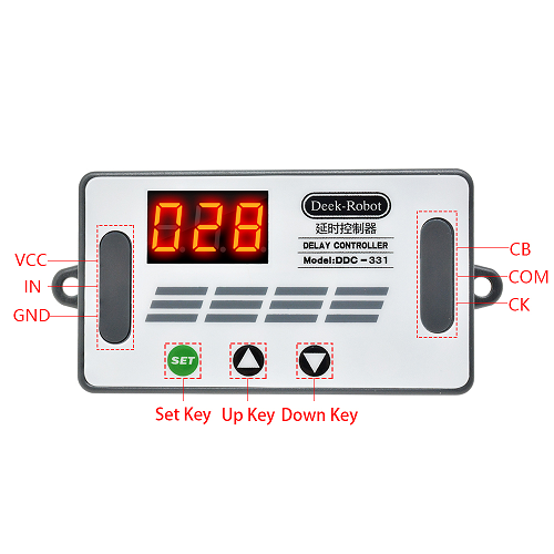
 Design with DEL Automatisation Relais DDC-331 in Cirkit Designer
Introduction
The DEL Automatisation Relais DDC-331 is a versatile relay module manufactured by abra (Part ID: MOD-DDC-331). This module is designed for automation applications, enabling the control of high-power electrical devices using low-voltage control signals. It provides electrical isolation between the control circuit and the load, ensuring safety and reliability in various applications.
Explore Projects Built with DEL Automatisation Relais DDC-331
 Open Project in Cirkit Designer
 Open Project in Cirkit Designer
 Open Project in Cirkit Designer
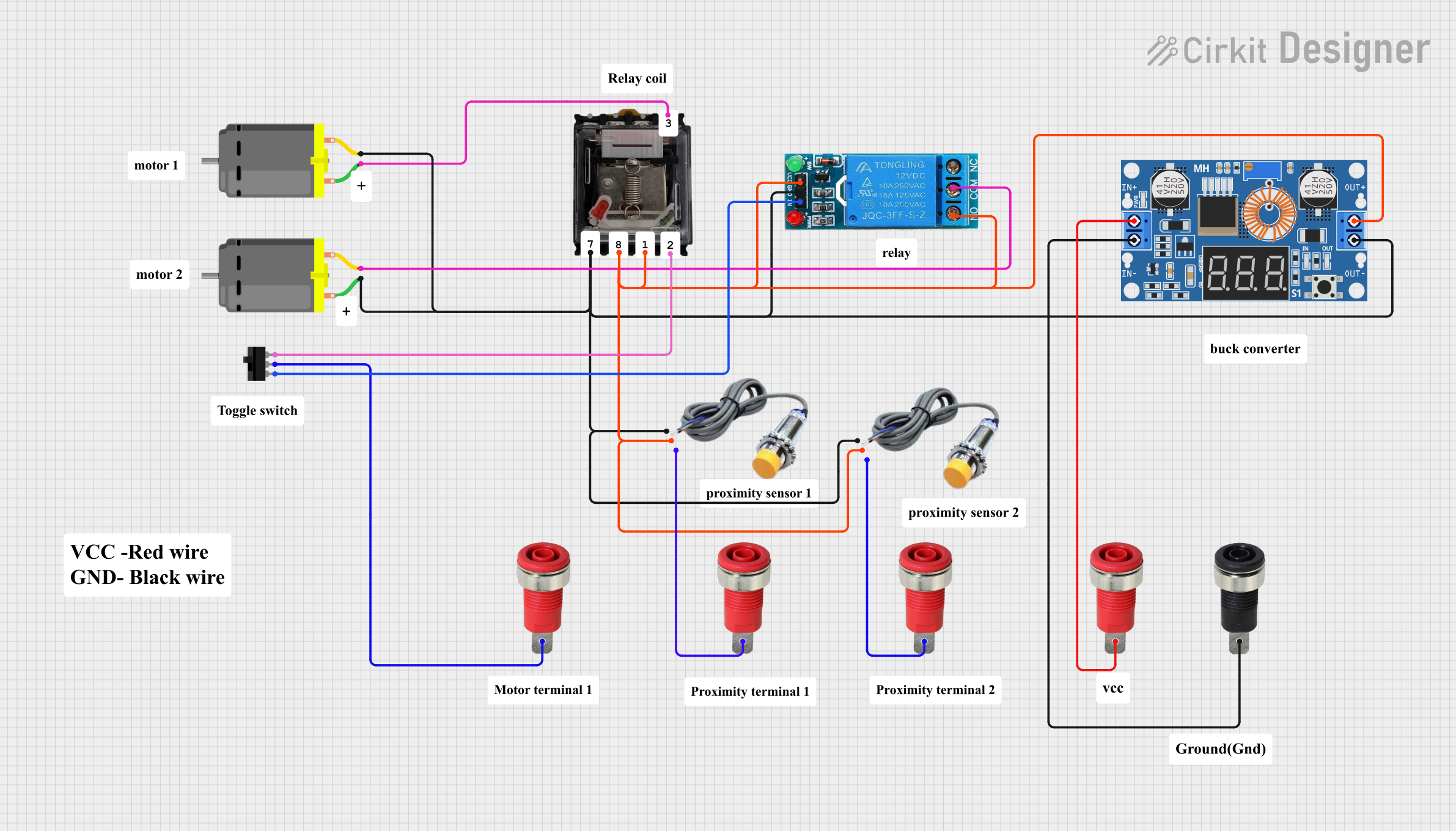 Open Project in Cirkit Designer
Explore Projects Built with DEL Automatisation Relais DDC-331
Open Project in Cirkit DesignerOpen Project in Cirkit DesignerOpen Project in Cirkit DesignerOpen Project in Cirkit DesignerCommon Applications and Use Cases
- Home automation systems (e.g., controlling lights, fans, or appliances)
- Industrial automation for switching motors, pumps, or solenoids
- Robotics and mechatronics for controlling actuators
- IoT projects requiring high-power load control
- Signal isolation in sensitive electronic systems
Technical Specifications
The following table outlines the key technical details of the DEL Automatisation Relais DDC-331:
| Parameter | Value |
|---|---|
| Operating Voltage | 5V DC |
| Trigger Voltage | 3.3V to 5V DC |
| Relay Output Voltage | Up to 250V AC / 30V DC |
| Relay Output Current | Up to 10A |
| Number of Relays | 4 |
| Isolation Method | Optocoupler |
| Dimensions | 70mm x 50mm x 20mm |
| Mounting Type | PCB Mount or Screw Mount |
| Operating Temperature | -20°C to 70°C |
Pin Configuration and Descriptions
The DEL Automatisation Relais DDC-331 features a straightforward pinout for easy integration into circuits. Below is the pin configuration:
Input Pins
| Pin Name | Description |
|---|---|
| VCC | Power supply input (5V DC) |
| GND | Ground connection |
| IN1 | Control signal for Relay 1 (Active HIGH) |
| IN2 | Control signal for Relay 2 (Active HIGH) |
| IN3 | Control signal for Relay 3 (Active HIGH) |
| IN4 | Control signal for Relay 4 (Active HIGH) |
Output Terminals (Relay Contacts)
| Terminal | Description |
|---|---|
| NO1 | Normally Open contact for Relay 1 |
| COM1 | Common contact for Relay 1 |
| NC1 | Normally Closed contact for Relay 1 |
| NO2 | Normally Open contact for Relay 2 |
| COM2 | Common contact for Relay 2 |
| NC2 | Normally Closed contact for Relay 2 |
| NO3 | Normally Open contact for Relay 3 |
| COM3 | Common contact for Relay 3 |
| NC3 | Normally Closed contact for Relay 3 |
| NO4 | Normally Open contact for Relay 4 |
| COM4 | Common contact for Relay 4 |
| NC4 | Normally Closed contact for Relay 4 |
Usage Instructions
How to Use the Component in a Circuit
- Power the Module: Connect the VCC pin to a 5V DC power source and the GND pin to the ground of your circuit.
- Connect Control Signals: Use digital output pins from a microcontroller (e.g., Arduino UNO) to send HIGH or LOW signals to the IN1, IN2, IN3, and IN4 pins to control the relays.
- Connect the Load: Wire the load to the relay output terminals (NO, NC, and COM) based on your switching requirements:
- Use the NO (Normally Open) terminal if the load should be off by default and turn on when the relay is activated.
- Use the NC (Normally Closed) terminal if the load should be on by default and turn off when the relay is activated.
- Test the Circuit: Verify the connections and test the relay switching by toggling the control signals.
Important Considerations and Best Practices
- Ensure the load does not exceed the relay's maximum voltage (250V AC / 30V DC) or current (10A).
- Use proper insulation and safety precautions when working with high-voltage loads.
- Avoid rapid switching of relays to prevent wear and tear on the mechanical contacts.
- Use a flyback diode across inductive loads (e.g., motors) to protect the relay from voltage spikes.
Example: Using the DDC-331 with an Arduino UNO
Below is an example Arduino sketch to control the relays:
// Define relay control pins
#define RELAY1 2  // Relay 1 connected to digital pin 2
#define RELAY2 3  // Relay 2 connected to digital pin 3
#define RELAY3 4  // Relay 3 connected to digital pin 4
#define RELAY4 5  // Relay 4 connected to digital pin 5

void setup() {
  // Set relay pins as outputs
  pinMode(RELAY1, OUTPUT);
  pinMode(RELAY2, OUTPUT);
  pinMode(RELAY3, OUTPUT);
  pinMode(RELAY4, OUTPUT);

  // Initialize all relays to OFF state
  digitalWrite(RELAY1, LOW);
  digitalWrite(RELAY2, LOW);
  digitalWrite(RELAY3, LOW);
  digitalWrite(RELAY4, LOW);
}

void loop() {
  // Example: Turn relays on and off sequentially
  digitalWrite(RELAY1, HIGH); // Turn on Relay 1
  delay(1000);                // Wait for 1 second
  digitalWrite(RELAY1, LOW);  // Turn off Relay 1

  digitalWrite(RELAY2, HIGH); // Turn on Relay 2
  delay(1000);                // Wait for 1 second
  digitalWrite(RELAY2, LOW);  // Turn off Relay 2

  digitalWrite(RELAY3, HIGH); // Turn on Relay 3
  delay(1000);                // Wait for 1 second
  digitalWrite(RELAY3, LOW);  // Turn off Relay 3

  digitalWrite(RELAY4, HIGH); // Turn on Relay 4
  delay(1000);                // Wait for 1 second
  digitalWrite(RELAY4, LOW);  // Turn off Relay 4
}
Troubleshooting and FAQs
Common Issues Users Might Face
- Relays Not Switching:
- Ensure the control signal voltage is within the specified range (3.3V to 5V).
- Verify that the VCC and GND connections are secure and powered correctly.
- Load Not Responding:
- Check the wiring of the load to the relay output terminals (NO, NC, and COM).
- Confirm that the load does not exceed the relay's voltage or current ratings.
- Relay Module Overheating:
- Ensure the load current is within the specified limit (10A).
- Avoid prolonged activation of relays under high loads.
Solutions and Tips for Troubleshooting
- Use a multimeter to check the continuity of the relay contacts when activated.
- Test the control signals from the microcontroller using an LED or oscilloscope.
- If using inductive loads, ensure a flyback diode is installed to protect the relay.
By following this documentation, users can effectively integrate the DEL Automatisation Relais DDC-331 into their projects and troubleshoot common issues with ease.