How to Use Teensy 4.0: Examples, Pinouts, and Specs
Introduction
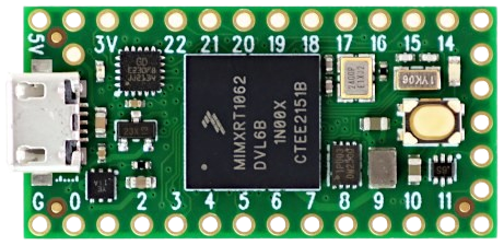
The Teensy 4.0 is a high-performance microcontroller board designed and manufactured by PJRC. It is based on the 32-bit ARM Cortex-M7 processor, which runs at a clock speed of 600 MHz, making it one of the fastest microcontrollers in the market suitable for a wide range of applications. Its compact size, extensive I/O capabilities, and low power consumption make it ideal for projects requiring significant processing power without sacrificing space or energy efficiency.
Common applications of the Teensy 4.0 include:
- Advanced audio processing
- Real-time data analysis
- High-speed USB communication
- Complex LED animations
- Robotics and control systems
- Prototyping Internet of Things (IoT) devices
Explore Projects Built with Teensy 4.0

Explore Projects Built with Teensy 4.0
Technical Specifications
Key Technical Details
- Processor: ARM Cortex-M7 at 600 MHz
- Flash Memory: 2 MB
- RAM: 1 MB
- Voltage: 3.3V logic, however, most digital pins are 5V tolerant
- Current: Can supply up to 250 mA at 3.3V
- Digital I/O Pins: 40 (including 31 PWM capable)
- Analog Inputs: 14 (2 ADCs on chip)
- Analog Outputs: 2 (DACs on chip)
- Serial Ports: 7
- I2C Ports: 3
- SPI Ports: 3
- CAN Bus Ports: 1
Pin Configuration and Descriptions
| Pin Number | Function | Description |
|---|---|---|
| 1-14 | Digital Pins | Digital I/O, PWM capable, 5V tolerant |
| 15-28 | Digital Pins | Digital I/O, PWM capable, 5V tolerant |
| 29-34 | Analog Inputs | High-resolution analog to digital converters |
| 35-36 | Analog Outputs | Digital to analog converters |
| 37-40 | Special | Serial, I2C, SPI, CAN, and other communication interfaces |
Usage Instructions
Integrating Teensy 4.0 into a Circuit
Powering the Teensy 4.0: Connect a 3.3V power supply to the VCC and GND pins. The board can also be powered via the USB port.
Programming the Teensy 4.0: Install the Teensyduino add-on for the Arduino IDE to program the Teensy 4.0. Select the appropriate board and port before uploading your code.
Connecting I/O: Use the digital and analog pins to interface with sensors, actuators, and other components. Ensure that the voltage levels are compatible.
Serial Communication: Utilize the serial ports for communication with other microcontrollers, computers, or peripherals.
Using SPI/I2C/CAN: Connect devices that support these protocols to the respective pins, ensuring correct pin mapping and voltage levels.
Best Practices
- Always check the pinout diagram before connecting components to avoid damage.
- Use a current limiting resistor when connecting LEDs to the digital pins.
- When using analog inputs, ensure that the voltage does not exceed 3.3V.
- For high-speed applications, keep wiring as short as possible to reduce noise and signal degradation.
- Utilize the onboard EEPROM for persistent data storage.
Troubleshooting and FAQs
Common Issues
- Teensy not recognized by the computer: Ensure the USB cable is properly connected and the board is receiving power. Try a different USB port or cable if necessary.
- Incorrect behavior of I/O pins: Verify that the pin configuration in your code matches the physical connections. Check for shorts or incorrect wiring.
- Inconsistent analog readings: Ensure that there is a stable power supply and that the analog reference voltage is set correctly in the software.
FAQs
Q: Can I power the Teensy 4.0 with 5V? A: No, the Teensy 4.0 operates at 3.3V. Applying 5V directly to the VCC pin can damage the board.
Q: Is the Teensy 4.0 compatible with Arduino shields? A: The Teensy 4.0 is not directly compatible with most Arduino shields due to its different pin layout. However, adapter shields are available to facilitate compatibility.
Q: How do I use the onboard DACs?
A: The DACs can be used by writing analog values using the analogWrite() function in your code, specifying the DAC pin number.
Q: What is the maximum current that the Teensy 4.0 can supply? A: The Teensy 4.0 can supply up to 250 mA at 3.3V from its onboard regulator.
For further assistance, consult the Teensy forums or the extensive documentation available on the PJRC website.
Example Code for Arduino UNO
Here is a simple example of how to blink an LED connected to pin 13 on the Teensy 4.0 using the Arduino IDE:
// Blink an LED connected to pin 13

void setup() {
  pinMode(13, OUTPUT); // Set pin 13 as an output
}

void loop() {
  digitalWrite(13, HIGH); // Turn the LED on
  delay(1000);           // Wait for a second
  digitalWrite(13, LOW);  // Turn the LED off
  delay(1000);           // Wait for a second
}
Remember to select the correct board (Teensy 4.0) in the Arduino IDE before uploading the code.