How to Use Hydraulic Solenoid Valve: Examples, Pinouts, and Specs
Introduction
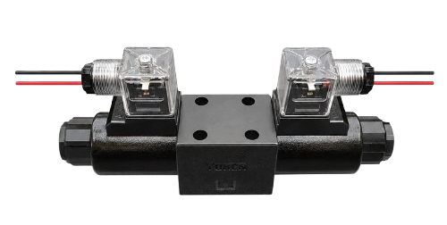
A hydraulic solenoid valve is an electromechanical device designed to control the flow of hydraulic fluid in a system. It operates by using an electromagnetic solenoid to open or close the valve, enabling precise control of hydraulic operations. These valves are widely used in industrial machinery, automotive systems, and heavy equipment where accurate fluid control is essential.
Explore Projects Built with Hydraulic Solenoid Valve
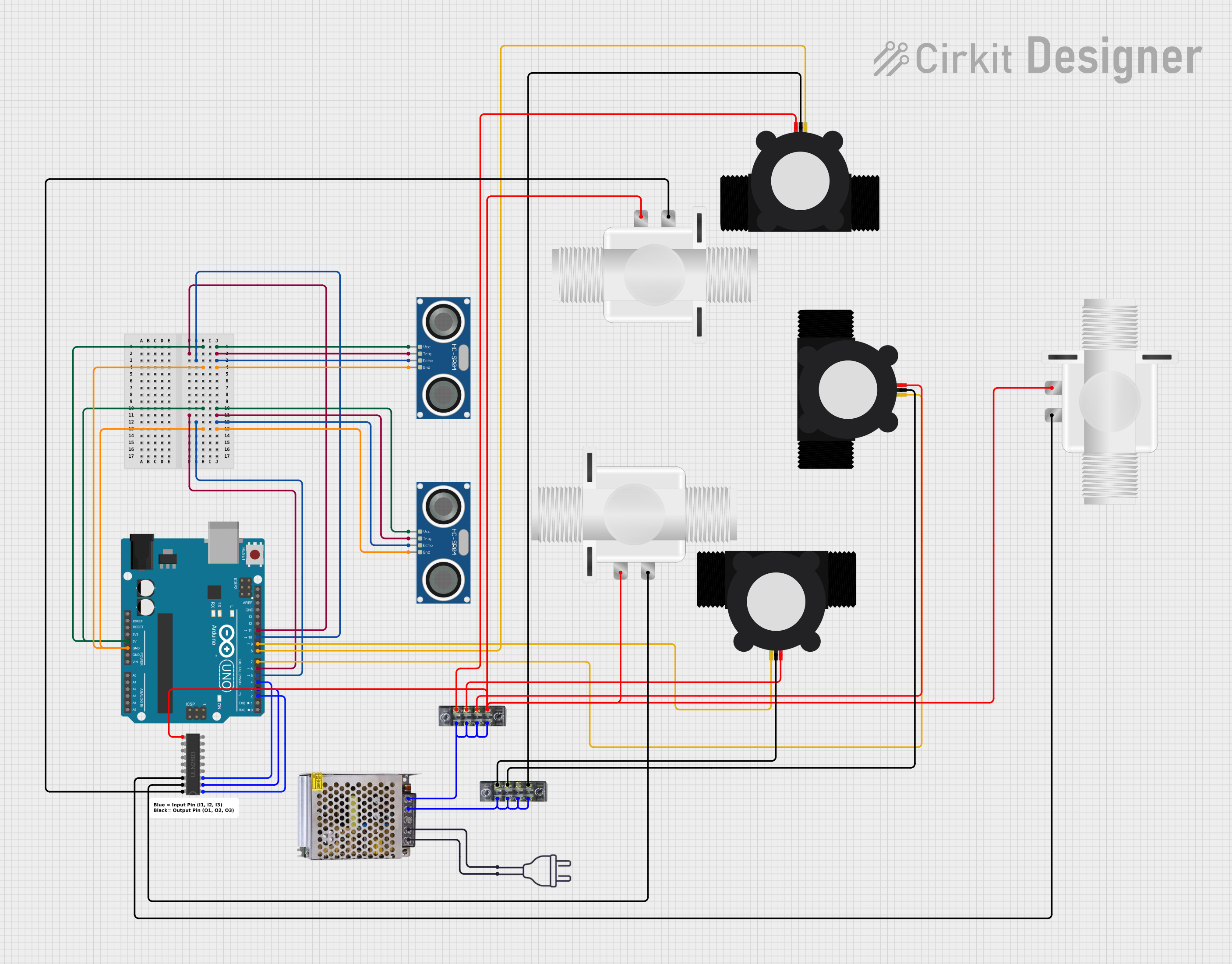
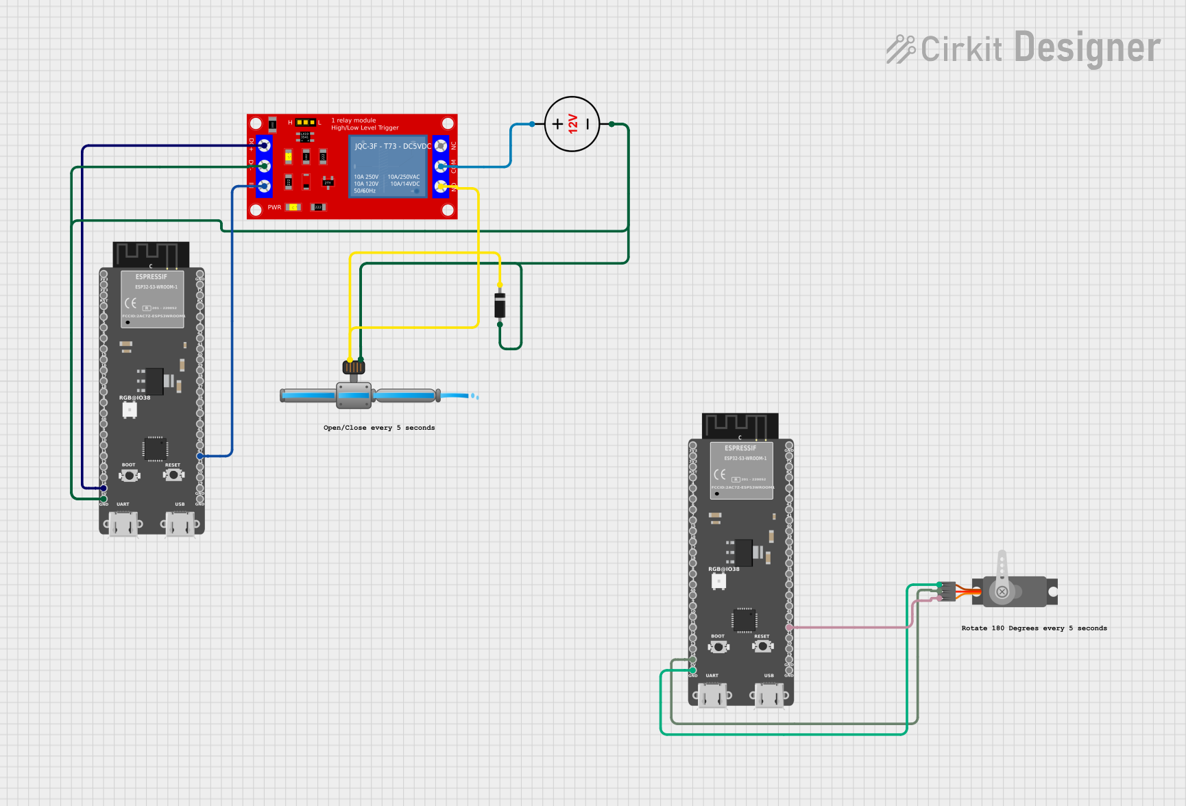

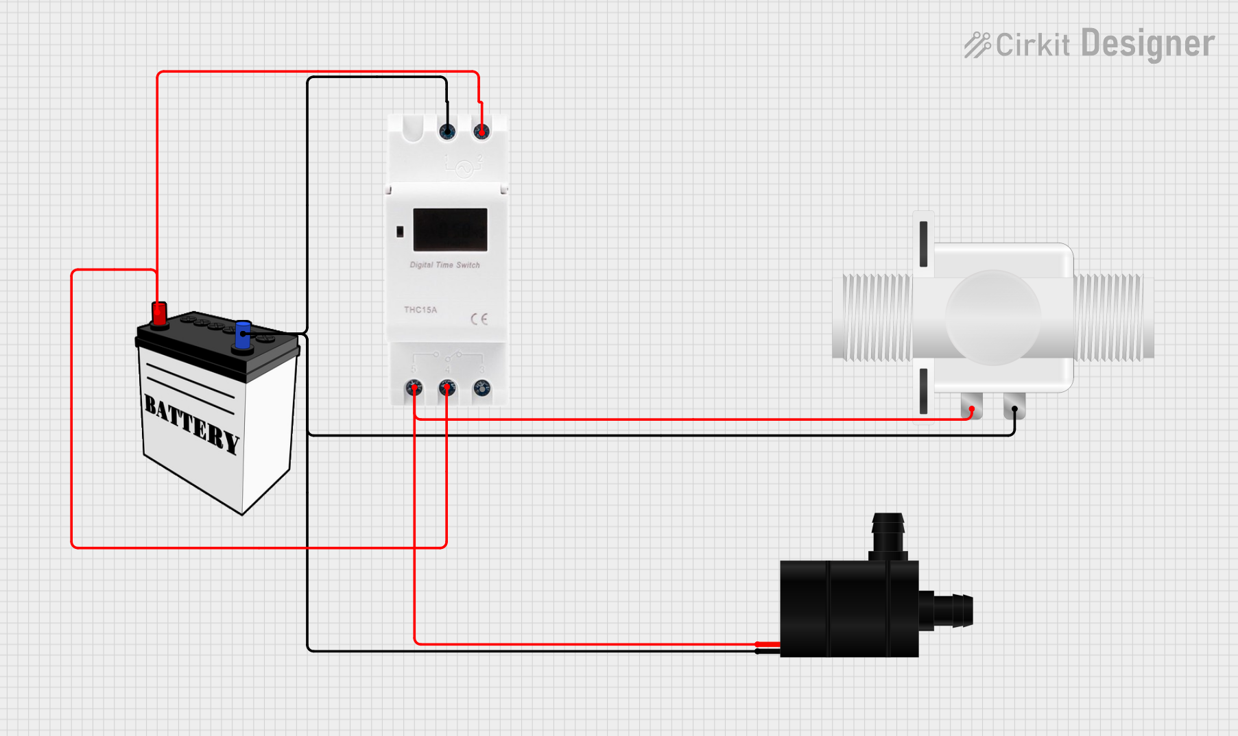
Explore Projects Built with Hydraulic Solenoid Valve
Common Applications and Use Cases
- Industrial automation systems
- Hydraulic presses and lifts
- Construction and agricultural machinery
- Automotive braking and transmission systems
- Fluid power systems in manufacturing equipment
Technical Specifications
Below are the key technical details and pin configuration for a typical hydraulic solenoid valve:
Key Technical Details
| Parameter | Specification |
|---|---|
| Operating Voltage | 12V DC, 24V DC, or 110-240V AC |
| Power Consumption | 5W to 30W (varies by model) |
| Operating Pressure Range | 0 to 350 bar (varies by application) |
| Flow Rate | 1 to 100 liters per minute (L/min) |
| Response Time | 10 to 50 milliseconds |
| Temperature Range | -20°C to 80°C |
| Material | Stainless steel, brass, or aluminum |
| Seal Type | Nitrile (NBR), Viton, or PTFE |
Pin Configuration and Descriptions
Hydraulic solenoid valves typically have two electrical connections for the solenoid coil. These connections are often labeled as follows:
| Pin Number | Label | Description |
|---|---|---|
| 1 | Positive (+) | Connect to the positive terminal of the power supply. |
| 2 | Negative (-) | Connect to the negative terminal of the power supply. |
Note: Some models may include additional pins for grounding or feedback signals. Always refer to the manufacturer's datasheet for specific details.
Usage Instructions
How to Use the Component in a Circuit
- Power Supply Selection: Ensure the power supply matches the operating voltage of the solenoid valve (e.g., 12V DC or 24V DC). Use a regulated power source to avoid voltage fluctuations.
- Wiring: Connect the positive terminal of the power supply to the positive pin of the solenoid coil and the negative terminal to the negative pin.
- Control Signal: Use a switch, relay, or microcontroller (e.g., Arduino) to control the solenoid valve. When the solenoid is energized, the valve opens or closes depending on its configuration (normally open or normally closed).
- Hydraulic Connections: Connect the inlet and outlet ports of the valve to the hydraulic system using appropriate fittings. Ensure the flow direction matches the markings on the valve body.
- Testing: After installation, test the valve operation by applying the control signal and observing the hydraulic flow.
Important Considerations and Best Practices
- Voltage Compatibility: Always verify the voltage rating of the solenoid coil before connecting it to a power source.
- Overheating Prevention: Avoid continuous energization of the solenoid for extended periods to prevent overheating.
- Hydraulic Fluid Compatibility: Ensure the valve's seals and materials are compatible with the hydraulic fluid used in your system.
- Mounting Orientation: Install the valve in the recommended orientation to ensure proper operation and avoid leaks.
- Debris Prevention: Use filters in the hydraulic system to prevent debris from clogging the valve.
Example: Controlling a Hydraulic Solenoid Valve with Arduino UNO
Below is an example of how to control a 12V DC hydraulic solenoid valve using an Arduino UNO and a relay module:
// Example: Controlling a hydraulic solenoid valve with Arduino UNO
// This code energizes the solenoid valve for 5 seconds, then de-energizes it.

const int relayPin = 7; // Pin connected to the relay module

void setup() {
  pinMode(relayPin, OUTPUT); // Set the relay pin as an output
  digitalWrite(relayPin, LOW); // Ensure the relay is off initially
}

void loop() {
  digitalWrite(relayPin, HIGH); // Turn on the relay (energize solenoid)
  delay(5000); // Keep the solenoid valve open for 5 seconds
  digitalWrite(relayPin, LOW); // Turn off the relay (de-energize solenoid)
  delay(5000); // Wait for 5 seconds before repeating
}
Note: Use a relay module capable of handling the solenoid's current requirements. A flyback diode should be installed across the solenoid terminals to protect the circuit from voltage spikes.
Troubleshooting and FAQs
Common Issues and Solutions
| Issue | Possible Cause | Solution |
|---|---|---|
| Valve does not operate | Incorrect wiring or insufficient voltage | Verify wiring and ensure correct voltage. |
| Solenoid overheating | Continuous energization | Use a duty cycle or reduce energization time. |
| Hydraulic fluid leakage | Damaged seals or improper connections | Inspect seals and fittings; replace if necessary. |
| Slow response time | Clogged valve or low power supply | Clean the valve and check the power supply. |
| No hydraulic flow | Incorrect flow direction or blockage | Verify flow direction and check for obstructions. |
FAQs
Can I use a hydraulic solenoid valve with AC power?
- Yes, but ensure the valve is rated for AC operation. Some models are designed specifically for AC power.
What happens if I reverse the polarity of the solenoid connections?
- Reversing polarity may damage the solenoid coil. Always follow the correct wiring instructions.
How do I know if the valve is normally open (NO) or normally closed (NC)?
- This information is typically marked on the valve body or specified in the datasheet.
Can I control multiple valves with a single Arduino?
- Yes, but you will need a separate relay or driver circuit for each valve to handle the current requirements.
By following this documentation, you can effectively integrate and troubleshoot a hydraulic solenoid valve in your system.