How to Use LVDT: Examples, Pinouts, and Specs
Introduction
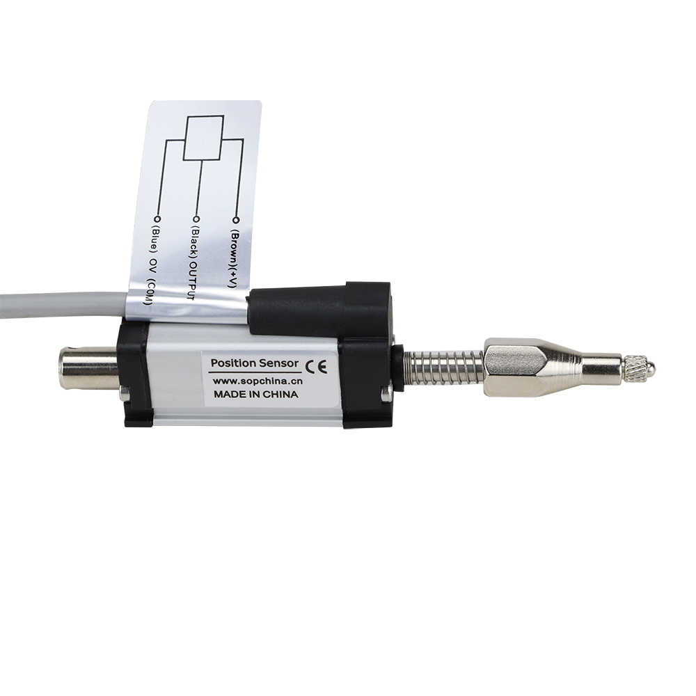
The Linear Variable Differential Transformer (LVDT), part number KTR18C-R-5, manufactured by Jiangxi Sop Precision Intelligent Manufacturing Technology Co., Ltd, is an electromechanical device designed for precise linear displacement measurement. It operates on the principle of electromagnetic induction, offering high accuracy, repeatability, and resolution. The LVDT is widely used in industrial automation, aerospace, robotics, and medical equipment for position sensing and feedback control.
Explore Projects Built with LVDT

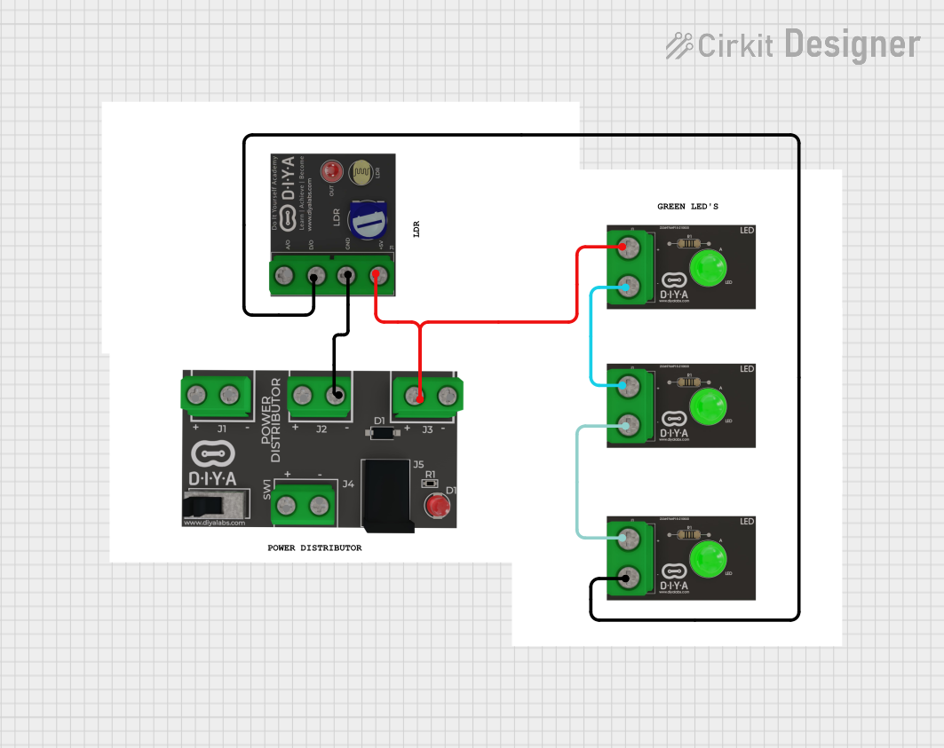
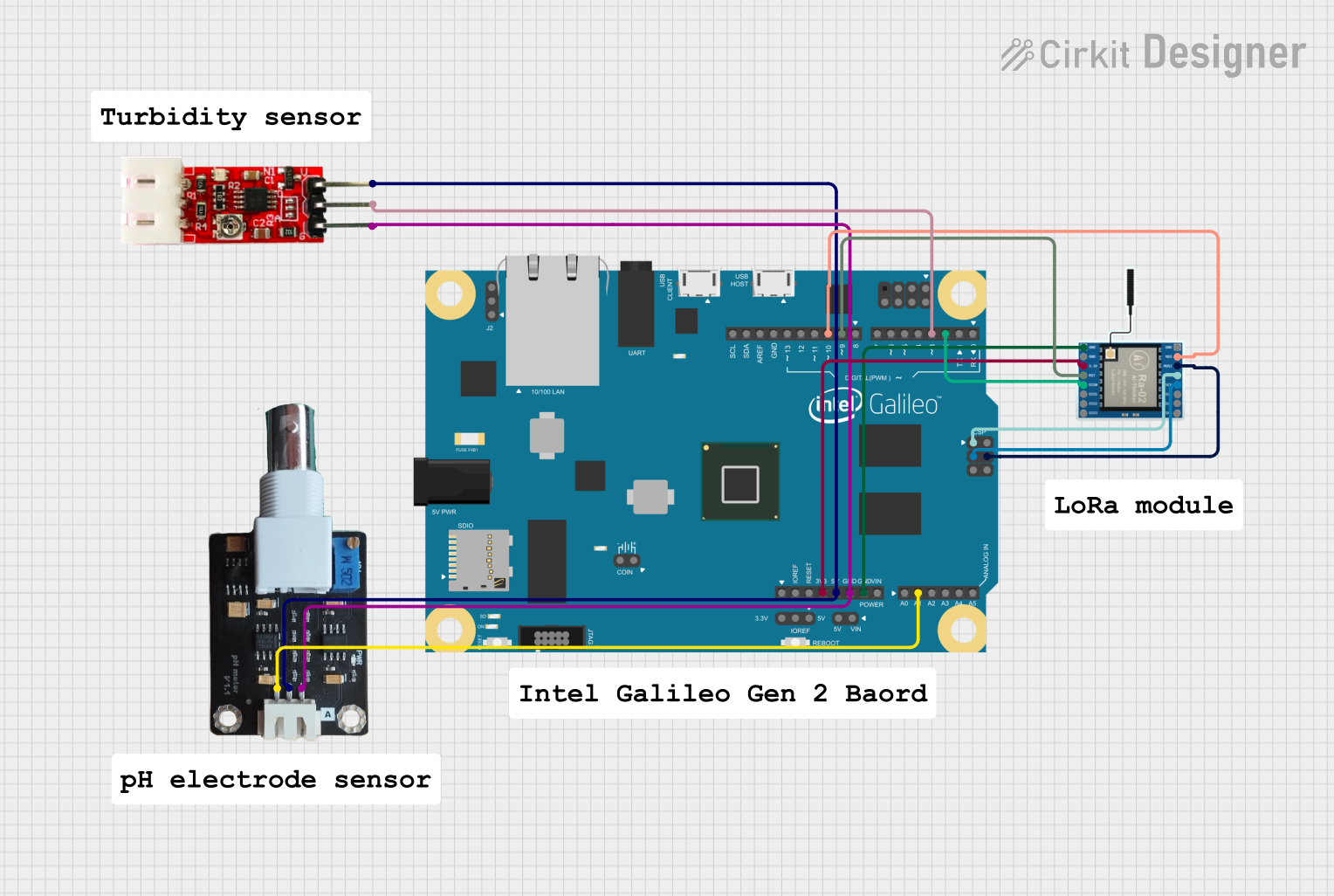
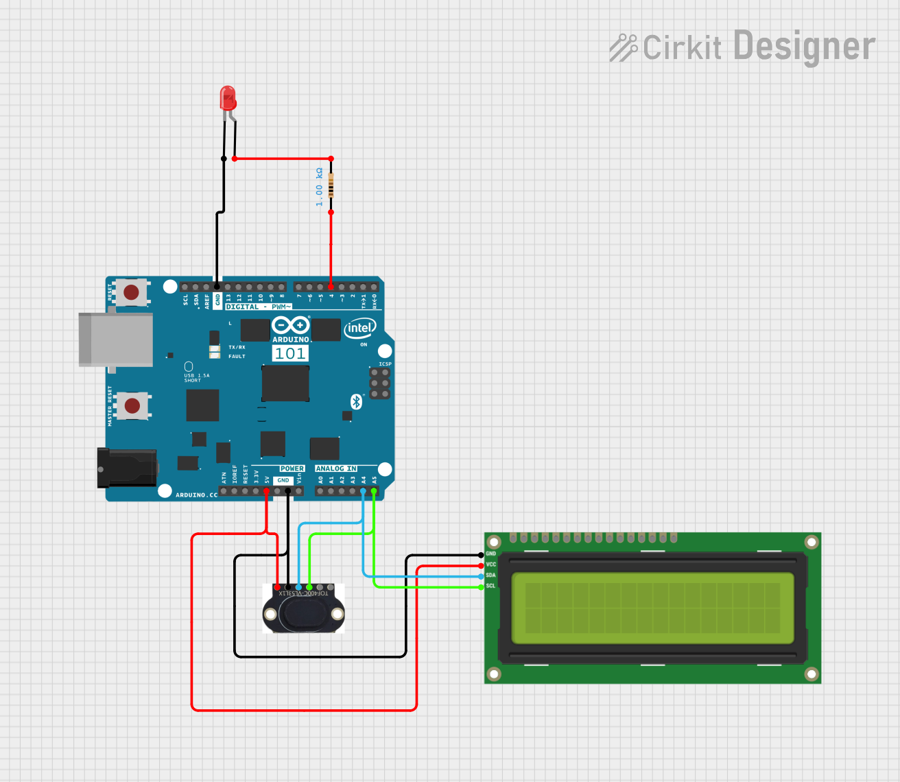
Explore Projects Built with LVDT
Common Applications
- Industrial automation for position feedback in hydraulic or pneumatic systems
- Aerospace systems for flight control and structural monitoring
- Robotics for precise motion control
- Medical devices such as MRI-compatible sensors
- Material testing machines for displacement measurement
Technical Specifications
Key Technical Details
| Parameter | Value |
|---|---|
| Manufacturer | Jiangxi Sop Precision Intelligent Manufacturing Technology Co., Ltd |
| Part Number | KTR18C-R-5 |
| Measurement Range | ±5 mm |
| Input Voltage | 3 V to 15 V RMS (AC) |
| Output Voltage | Proportional to displacement |
| Sensitivity | 2.5 mV/V/mm |
| Linearity Error | ±0.25% of full scale |
| Operating Frequency | 2 kHz to 10 kHz |
| Operating Temperature Range | -40°C to +85°C |
| Housing Material | Stainless Steel |
| Core Material | Nickel-Iron Alloy |
| Electrical Connection | 6-pin connector |
Pin Configuration and Descriptions
| Pin Number | Name | Description |
|---|---|---|
| 1 | Primary Coil | Connect to the AC excitation source (input) |
| 2 | Primary Coil | Connect to the AC excitation source (input) |
| 3 | Secondary Coil A | Differential output signal (phase A) |
| 4 | Secondary Coil A | Differential output signal (phase A) |
| 5 | Secondary Coil B | Differential output signal (phase B) |
| 6 | Secondary Coil B | Differential output signal (phase B) |
Usage Instructions
How to Use the LVDT in a Circuit
- Power Supply: Provide an AC excitation voltage (3 V to 15 V RMS) to the primary coil (pins 1 and 2). The excitation frequency should be within the range of 2 kHz to 10 kHz.
- Signal Processing: Connect the secondary coils (pins 3, 4, 5, and 6) to a signal conditioning circuit or LVDT signal processor. The output voltage will vary proportionally to the displacement of the core.
- Core Movement: Ensure the core is free to move linearly within the LVDT housing. The displacement of the core will induce a differential voltage in the secondary coils.
- Output Measurement: Measure the differential output voltage to determine the position of the core. Use a calibrated signal processor to convert the voltage into displacement units.
Important Considerations and Best Practices
- Alignment: Ensure the LVDT is properly aligned with the moving object to avoid measurement errors.
- Excitation Source: Use a stable and noise-free AC excitation source for accurate results.
- Temperature Effects: Operate the LVDT within the specified temperature range (-40°C to +85°C) to maintain accuracy.
- Shielding: Use proper shielding to minimize electromagnetic interference (EMI) in noisy environments.
- Calibration: Periodically calibrate the LVDT with a known displacement standard to ensure accuracy.
Example: Connecting the LVDT to an Arduino UNO
To interface the LVDT with an Arduino UNO, you will need an LVDT signal conditioner to convert the differential output into a readable DC voltage. Below is an example code snippet for reading the conditioned output using the Arduino's analog input:
// Example code for reading LVDT output with Arduino UNO
// Ensure the LVDT signal conditioner is connected to the Arduino's analog input

const int lvdtPin = A0; // Analog pin connected to the LVDT signal conditioner
float voltage = 0.0;    // Variable to store the measured voltage
float displacement = 0.0; // Variable to store the calculated displacement

// Calibration factor (depends on the LVDT sensitivity and signal conditioner output)
// Adjust this value based on your specific setup
const float calibrationFactor = 2.5; // Example: 2.5 mm/V

void setup() {
  Serial.begin(9600); // Initialize serial communication
}

void loop() {
  voltage = analogRead(lvdtPin) * (5.0 / 1023.0); // Convert ADC value to voltage
  displacement = voltage * calibrationFactor;    // Calculate displacement
  Serial.print("Voltage: ");
  Serial.print(voltage);
  Serial.print(" V, Displacement: ");
  Serial.print(displacement);
  Serial.println(" mm");
  delay(500); // Delay for readability
}
Troubleshooting and FAQs
Common Issues and Solutions
No Output Signal
- Cause: No excitation voltage applied to the primary coil.
- Solution: Verify the AC excitation source is connected and operating within the specified voltage and frequency range.
Inaccurate Measurements
- Cause: Misalignment of the LVDT or core binding.
- Solution: Ensure proper alignment and that the core moves freely without friction.
Noise in Output Signal
- Cause: Electromagnetic interference (EMI) or unstable excitation source.
- Solution: Use shielded cables and a stable, noise-free excitation source.
Output Signal Saturation
- Cause: Core displacement exceeds the measurement range.
- Solution: Ensure the core remains within the specified ±5 mm range.
FAQs
Q1: Can the LVDT be used in a DC circuit?
A1: No, the LVDT requires an AC excitation source to operate. A signal conditioner is needed to convert the output for use in DC systems.
Q2: How do I calibrate the LVDT?
A2: Use a known displacement standard and adjust the signal conditioner or processing circuit to match the output voltage to the corresponding displacement.
Q3: What happens if the core is removed from the LVDT?
A3: The output signal will drop to zero or become unstable, as the core is essential for inducing the differential voltage in the secondary coils.
Q4: Can the LVDT operate in harsh environments?
A4: Yes, the stainless steel housing and wide operating temperature range make it suitable for harsh industrial environments. However, ensure proper sealing against contaminants.
This concludes the documentation for the KTR18C-R-5 LVDT. For further assistance, refer to the manufacturer's datasheet or contact technical support.