How to Use boost converter: Examples, Pinouts, and Specs
Introduction
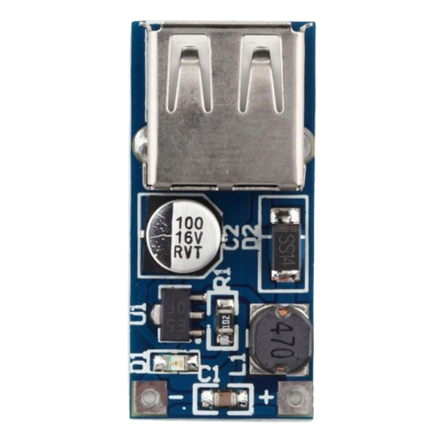
A boost converter is a DC-DC power converter that steps up (increases) the input voltage to a higher output voltage while maintaining the same polarity. It operates using an inductor, a switch (typically a transistor), a diode, and a capacitor to achieve efficient voltage conversion. Boost converters are widely used in applications where a higher voltage is required from a lower voltage source, such as in battery-powered devices, renewable energy systems, and automotive electronics.
Explore Projects Built with boost converter


Explore Projects Built with boost converter
Common Applications and Use Cases
- Powering high-voltage devices from low-voltage batteries (e.g., LED drivers, portable electronics)
- Solar power systems to step up panel voltage for charging batteries
- Electric vehicles to boost battery voltage for motor operation
- Industrial and medical equipment requiring stable high-voltage outputs
Technical Specifications
Below are the general technical specifications for a typical boost converter. Note that actual values may vary depending on the specific model or design.
| Parameter | Value |
|---|---|
| Input Voltage Range | 2V to 36V (varies by design) |
| Output Voltage Range | Up to 60V (varies by design) |
| Output Current | Typically 0.5A to 10A (depends on design) |
| Efficiency | 80% to 95% (depending on load and design) |
| Switching Frequency | 100 kHz to 1 MHz |
| Operating Temperature | -40°C to +85°C |
Pin Configuration and Descriptions
The pin configuration of a boost converter module (e.g., a pre-assembled module) typically includes the following:
| Pin Name | Description |
|---|---|
| VIN | Input voltage pin (connect to the power source) |
| GND | Ground pin (common ground for input and output) |
| VOUT | Output voltage pin (connect to the load) |
| EN (optional) | Enable pin (used to turn the converter on/off) |
| FB (optional) | Feedback pin (used for voltage regulation and control) |
Usage Instructions
How to Use the Component in a Circuit
Connect the Input Voltage (VIN):
- Attach the positive terminal of the power source to the VIN pin.
- Connect the negative terminal of the power source to the GND pin.
Connect the Output Voltage (VOUT):
- Attach the load (e.g., an LED, motor, or other device) to the VOUT pin.
- Ensure the load's voltage and current requirements are within the boost converter's specifications.
Enable the Converter (if applicable):
- If the module has an EN (Enable) pin, connect it to a HIGH signal (e.g., 5V) to activate the converter.
- To disable the converter, connect the EN pin to GND.
Adjust the Output Voltage (if adjustable):
- Some boost converters have a potentiometer for adjusting the output voltage.
- Rotate the potentiometer clockwise or counterclockwise to increase or decrease the output voltage.
- Use a multimeter to measure the output voltage while adjusting.
Important Considerations and Best Practices
- Input Voltage Range: Ensure the input voltage is within the specified range of the boost converter. Exceeding this range can damage the module.
- Output Voltage Limit: Do not exceed the maximum output voltage rating of the converter.
- Heat Dissipation: Boost converters can generate heat during operation. Use a heatsink or ensure proper ventilation if the module gets too hot.
- Load Requirements: Verify that the load does not draw more current than the converter can supply.
- Ripple and Noise: Use additional capacitors at the input and output to reduce voltage ripple and noise, especially in sensitive applications.
Example: Using a Boost Converter with Arduino UNO
A boost converter can be used to power devices requiring higher voltage than the Arduino UNO's 5V output. Below is an example of using a boost converter to power a 12V LED strip.
Circuit Connections
- Connect the Arduino's 5V pin to the VIN pin of the boost converter.
- Connect the GND pin of the Arduino to the GND pin of the boost converter.
- Adjust the boost converter's output to 12V using the potentiometer.
- Connect the VOUT pin of the boost converter to the positive terminal of the LED strip.
- Connect the negative terminal of the LED strip to the GND pin of the boost converter.
Arduino Code Example
// This code demonstrates controlling the LED strip using a PWM signal
// from the Arduino UNO. The PWM signal adjusts the brightness of the LED strip.

const int pwmPin = 9; // PWM pin connected to the LED strip (via a transistor)

void setup() {
  pinMode(pwmPin, OUTPUT); // Set the PWM pin as an output
}

void loop() {
  // Gradually increase brightness
  for (int brightness = 0; brightness <= 255; brightness++) {
    analogWrite(pwmPin, brightness); // Write PWM signal to the pin
    delay(10); // Small delay for smooth transition
  }

  // Gradually decrease brightness
  for (int brightness = 255; brightness >= 0; brightness--) {
    analogWrite(pwmPin, brightness); // Write PWM signal to the pin
    delay(10); // Small delay for smooth transition
  }
}
Troubleshooting and FAQs
Common Issues and Solutions
No Output Voltage:
- Cause: Input voltage is too low or not connected properly.
Solution: Verify the input voltage and connections. Ensure it is within the specified range. - Cause: EN pin is not enabled.
Solution: Check the EN pin and connect it to a HIGH signal if required.
- Cause: Input voltage is too low or not connected properly.
Output Voltage is Incorrect:
- Cause: Potentiometer is not adjusted correctly.
Solution: Use a multimeter to measure the output voltage and adjust the potentiometer.
- Cause: Potentiometer is not adjusted correctly.
Excessive Heat:
- Cause: Load is drawing too much current.
Solution: Reduce the load or use a boost converter with a higher current rating. - Cause: Poor ventilation.
Solution: Add a heatsink or improve airflow around the module.
- Cause: Load is drawing too much current.
High Ripple or Noise:
- Cause: Insufficient filtering.
Solution: Add additional capacitors at the input and output terminals.
- Cause: Insufficient filtering.
FAQs
Q: Can I use a boost converter to power a microcontroller?
A: Yes, but ensure the output voltage is stable and within the microcontroller's operating range. Use additional capacitors to reduce ripple.
Q: What happens if the input voltage exceeds the specified range?
A: Exceeding the input voltage range can damage the boost converter. Always use a power source within the recommended range.
Q: Can I use a boost converter to step down voltage?
A: No, a boost converter is designed to step up voltage. For stepping down voltage, use a buck converter instead.