
How to Use Header 2: Examples, Pinouts, and Specs
 Design with Header 2 in Cirkit Designer
Introduction
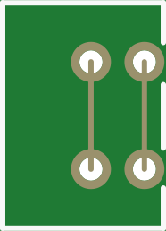
A Header 2 is a type of connector used to interface with printed circuit boards (PCBs). It typically features two rows of pins, making it ideal for connecting various electronic components or modules. These connectors are widely used in prototyping, embedded systems, and modular designs due to their simplicity and versatility. Header 2 connectors are available in male and female configurations, allowing for flexible interconnections.
Explore Projects Built with Header 2
 Open Project in Cirkit Designer
 Open Project in Cirkit Designer
 Open Project in Cirkit Designer
 Open Project in Cirkit Designer
Explore Projects Built with Header 2
Open Project in Cirkit DesignerOpen Project in Cirkit DesignerOpen Project in Cirkit DesignerOpen Project in Cirkit DesignerCommon Applications and Use Cases
- Connecting sensors, modules, or peripherals to microcontrollers
- Establishing communication between PCBs in multi-board systems
- Prototyping and breadboarding electronic circuits
- Modular designs for easy assembly and disassembly
- Power and signal transmission in embedded systems
Technical Specifications
Below are the key technical details for a standard Header 2 connector:
General Specifications
- Number of Rows: 2
- Pin Pitch: 2.54 mm (standard)
- Pin Count: Typically ranges from 2x2 to 2x40
- Current Rating: 1A to 3A per pin (varies by manufacturer)
- Voltage Rating: Up to 250V
- Operating Temperature: -40°C to +105°C
- Material: Gold-plated or tin-plated brass pins, plastic housing (e.g., PBT or nylon)
Pin Configuration and Descriptions
The pin configuration of a Header 2 connector depends on the number of pins and rows. Below is an example for a 2x4 (8-pin) Header 2 connector:
| Pin Number | Description | Notes |
|---|---|---|
| 1 | Signal/Power Line 1 | Can be used for data or power |
| 2 | Signal/Power Line 2 | Can be used for data or power |
| 3 | Signal/Power Line 3 | Can be used for data or power |
| 4 | Signal/Power Line 4 | Can be used for data or power |
| 5 | Ground (GND) | Common ground for the circuit |
| 6 | Ground (GND) | Common ground for the circuit |
| 7 | Signal/Power Line 5 | Can be used for data or power |
| 8 | Signal/Power Line 6 | Can be used for data or power |
Note: The pinout may vary depending on the specific application or manufacturer. Always refer to the datasheet for precise details.
Usage Instructions
How to Use the Component in a Circuit
- Soldering:
- Solder the Header 2 connector onto the PCB, ensuring proper alignment with the pads.
- Use a soldering iron with a fine tip for precision and avoid overheating the pins.
- Connecting Components:
- Insert the male Header 2 pins into the female counterpart or vice versa.
- Ensure a snug fit to maintain a reliable electrical connection.
- Wiring:
- Use jumper wires or ribbon cables to connect the Header 2 to other components or modules.
- Verify the pinout to avoid incorrect connections.
Important Considerations and Best Practices
- Pin Alignment: Double-check the orientation of the connector to prevent reversed connections.
- Current and Voltage Ratings: Ensure the current and voltage do not exceed the connector's specifications.
- Mechanical Stress: Avoid excessive force when inserting or removing connectors to prevent damage.
- Corrosion Prevention: Use gold-plated connectors for high-reliability applications to reduce oxidation.
Example: Connecting Header 2 to an Arduino UNO
Header 2 connectors are commonly used to interface sensors or modules with an Arduino UNO. Below is an example of connecting a 2x4 Header 2 to an Arduino UNO:
// Example: Reading data from a sensor connected via a Header 2 connector
// Pin 1: VCC (5V), Pin 2: GND, Pin 3: Data, Pin 4: Not connected

const int dataPin = 2; // Pin 3 of Header 2 connected to Arduino digital pin 2

void setup() {
  pinMode(dataPin, INPUT); // Set the data pin as input
  Serial.begin(9600);      // Initialize serial communication
}

void loop() {
  int sensorValue = digitalRead(dataPin); // Read the sensor value
  Serial.println(sensorValue);           // Print the value to the Serial Monitor
  delay(500);                            // Wait for 500ms before the next read
}
Note: Adjust the pin connections and code based on your specific sensor or module.
Troubleshooting and FAQs
Common Issues Users Might Face
Loose Connections:
- Problem: The connection between the male and female headers is not secure.
- Solution: Ensure the connectors are properly aligned and fully inserted.
Incorrect Pinout:
- Problem: The pins are connected incorrectly, causing the circuit to malfunction.
- Solution: Double-check the pinout and wiring before powering the circuit.
Overheating During Soldering:
- Problem: Excessive heat damages the plastic housing or pins.
- Solution: Use a temperature-controlled soldering iron and limit soldering time.
Corrosion or Oxidation:
- Problem: Poor electrical contact due to corroded pins.
- Solution: Use gold-plated connectors or clean the pins with isopropyl alcohol.
FAQs
Q1: Can I use a Header 2 connector for high-current applications?
A1: Header 2 connectors are typically rated for 1A to 3A per pin. For higher currents, consider using connectors specifically designed for power applications.
Q2: How do I prevent accidental disconnections?
A2: Use locking connectors or secure the connection with adhesive or cable ties.
Q3: Are Header 2 connectors compatible with breadboards?
A3: Yes, male Header 2 connectors with a 2.54 mm pitch are compatible with standard breadboards.
Q4: Can I cut a longer Header 2 strip to a custom size?
A4: Yes, you can cut the strip using a sharp blade or wire cutters. Be careful to avoid damaging the pins.
By following this documentation, you can effectively use Header 2 connectors in your electronic projects!