How to Use 4xAA_bare: Examples, Pinouts, and Specs

Introduction
The 4xAA battery holder is a simple and convenient way to power electronic projects. It holds four AA batteries in series, providing a nominal voltage of 6V (1.5V per cell) when using alkaline batteries, or 4.8V when using rechargeable NiMH cells. This component is commonly used in DIY projects, educational settings, robotics, and portable devices where a compact and reliable power source is needed.
Explore Projects Built with 4xAA_bare
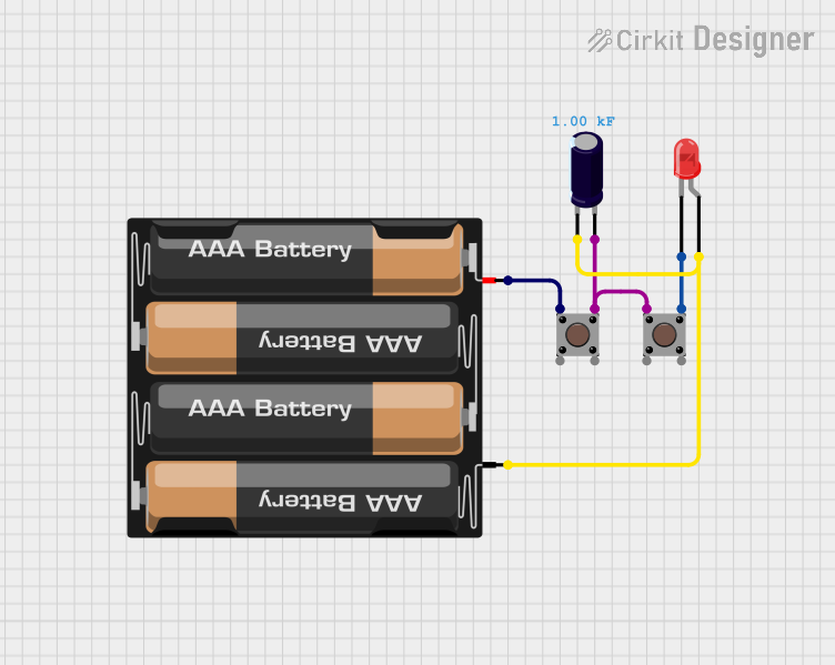
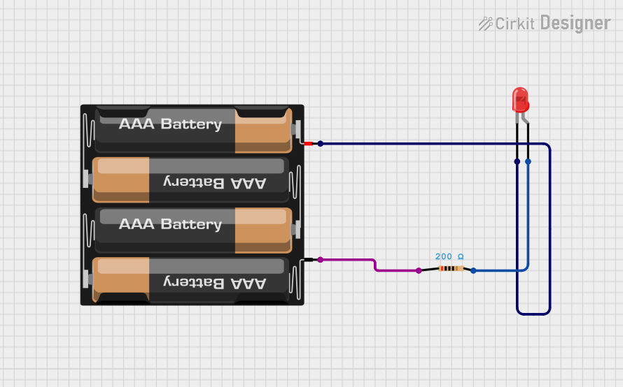
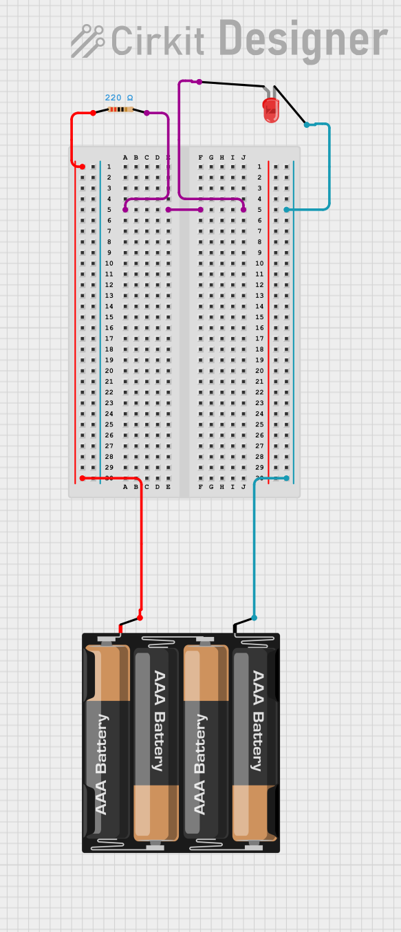

Explore Projects Built with 4xAA_bare
Common Applications and Use Cases
- Portable electronic devices
- DIY electronics projects
- Educational kits for teaching electronics
- Robotics and remote-controlled devices
- Temporary power for testing circuits
Technical Specifications
Key Technical Details
- Nominal Voltage: 6V with alkaline batteries, 4.8V with NiMH batteries
- Maximum Current: Dependent on the batteries used
- Material: Plastic casing with metal contacts
- Wire Leads: Typically 150mm to 200mm in length
- Connector Type: Bare wire leads
Pin Configuration and Descriptions
| Pin | Description |
|---|---|
| + | Positive lead (red wire) |
| - | Negative lead (black wire) |
Usage Instructions
How to Use the Component in a Circuit
- Inserting Batteries: Ensure the batteries are inserted following the correct polarity as indicated in the battery holder.
- Connecting to a Circuit: Strip the ends of the wire leads if necessary and solder or use a terminal block to connect the holder to your circuit.
- Securing the Holder: Use screws or double-sided tape to secure the battery holder in your project enclosure if needed.
Important Considerations and Best Practices
- Battery Orientation: Always check the polarity of the batteries before inserting them into the holder.
- Voltage Requirements: Ensure that the total voltage of the batteries matches the voltage requirements of your circuit.
- Current Limitations: Be aware of the current limitations of the batteries you are using to avoid overloading them.
- Battery Replacement: Replace all batteries at the same time to ensure balanced discharge and performance.
- Safety: Do not mix old and new batteries or different types of batteries to prevent leakage or damage.
Troubleshooting and FAQs
Common Issues
- Power not reaching the circuit: Check the batteries for proper insertion and ensure the wire leads are securely connected to the circuit.
- Intermittent power: Inspect the battery holder for any loose connections or damaged wires.
Solutions and Tips for Troubleshooting
- Secure Connections: Make sure all connections are tight and secure. Soldering the wire leads to the circuit can provide a more reliable connection than using terminal blocks.
- Battery Health: Use a multimeter to check the voltage of the batteries to ensure they are not depleted.
- Holder Inspection: Regularly inspect the battery holder for any signs of wear or damage, such as cracked plastic or corroded contacts.
FAQs
Q: Can I use rechargeable batteries with this holder? A: Yes, you can use rechargeable AA batteries, but keep in mind that they typically have a lower voltage per cell (1.2V), resulting in a total of 4.8V.
Q: What is the maximum current the battery holder can handle? A: The maximum current is dependent on the batteries used. Always refer to the specifications of the batteries for current ratings.
Q: How can I increase the voltage or capacity? A: To increase voltage, additional battery holders can be connected in series. To increase capacity, connect battery holders in parallel, ensuring all batteries are of the same type and charge level.
Example Code for Arduino UNO
// This example demonstrates how to power an Arduino UNO using the 4xAA battery holder.

void setup() {
  // Initialize the built-in LED pin as an output.
  pinMode(LED_BUILTIN, OUTPUT);
}

void loop() {
  // Turn the LED on (HIGH is the voltage level)
  digitalWrite(LED_BUILTIN, HIGH);
  // Wait for a second
  delay(1000);
  // Turn the LED off by making the voltage LOW
  digitalWrite(LED_BUILTIN, LOW);
  // Wait for a second
  delay(1000);
}
Note: When powering an Arduino UNO with the 4xAA battery holder, connect the positive lead to the Vin pin and the negative lead to one of the GND pins on the Arduino. Ensure that the voltage does not exceed the recommended input voltage for the Arduino UNO.