
How to Use 3 channel line tracking: Examples, Pinouts, and Specs
 Design with 3 channel line tracking in Cirkit Designer
Introduction
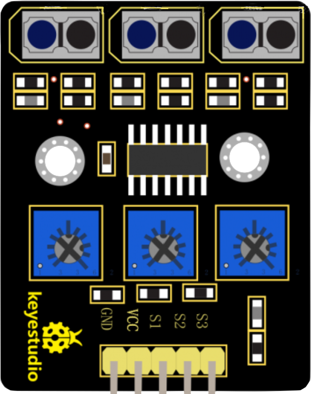
The Keyestudio KS0453 is a 3-channel line tracking sensor module designed for robotics and automation projects. It uses infrared light to detect the contrast between a line (usually black) and the background (usually white) on a surface. This module is commonly used in line-following robots, maze-solving robots, and other applications where path detection is required.
Explore Projects Built with 3 channel line tracking
 Open Project in Cirkit Designer
 Open Project in Cirkit Designer
 Open Project in Cirkit Designer
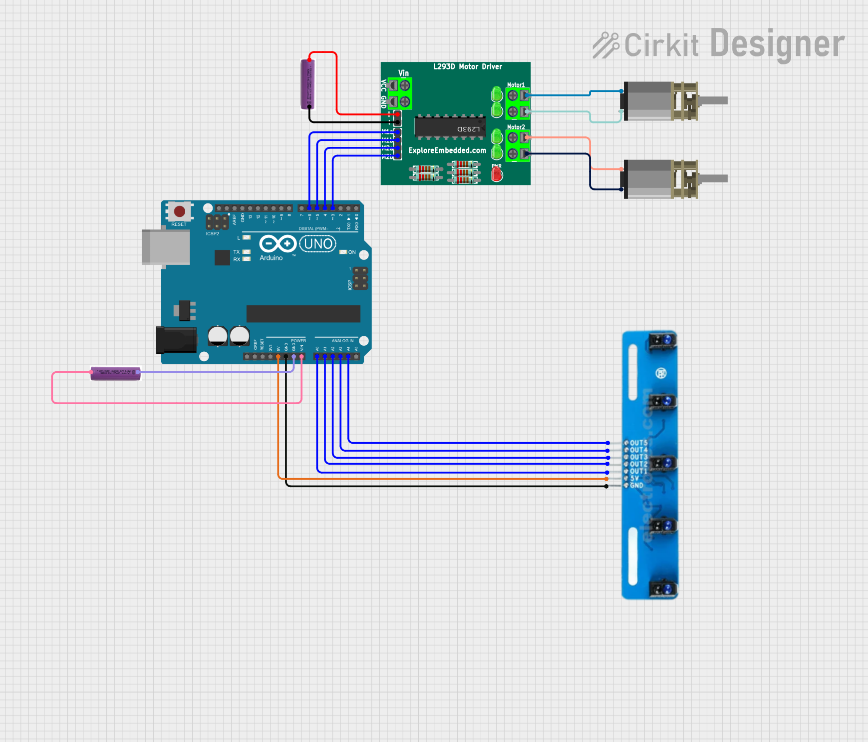
 Open Project in Cirkit Designer
Explore Projects Built with 3 channel line tracking

 Open Project in Cirkit Designer
 Open Project in Cirkit Designer
 Open Project in Cirkit Designer
 Open Project in Cirkit Designer
Common Applications
- Line-following robots
- Edge detection for navigating robots
- Automated guided vehicles (AGVs)
- Educational projects and robotics workshops
Technical Specifications
Key Technical Details
- Operating Voltage: 5V DC
- Output Channel: 3 digital signal outputs
- Output Voltage: 0V (Low, line detected) or 5V (High, no line detected)
- Response Time: <2ms
- Detection Distance: 10mm to 15mm
- Ambient Light Resistance: Good
- Operating Current: <20mA
- Sensor Type: Infrared reflection
- Dimensions: 42mm x 38mm x 12mm
Pin Configuration and Descriptions
| Pin Number | Pin Name | Description |
|---|---|---|
| 1 | VCC | Power supply (5V DC) |
| 2 | GND | Ground |
| 3 | OUT1 | Digital output for sensor 1 |
| 4 | OUT2 | Digital output for sensor 2 |
| 5 | OUT3 | Digital output for sensor 3 |
Usage Instructions
Connecting to an Arduino UNO
- Connect the VCC pin to the 5V output on the Arduino UNO.
- Connect the GND pin to one of the GND pins on the Arduino UNO.
- Connect OUT1, OUT2, and OUT3 to digital input pins on the Arduino UNO (e.g., pins 2, 3, and 4).
Sample Arduino Code
// Define the sensor pins
const int sensor1Pin = 2;
const int sensor2Pin = 3;
const int sensor3Pin = 4;

void setup() {
  // Set sensor pins as input
  pinMode(sensor1Pin, INPUT);
  pinMode(sensor2Pin, INPUT);
  pinMode(sensor3Pin, INPUT);

  // Begin serial communication at a baud rate of 9600
  Serial.begin(9600);
}

void loop() {
  // Read the state of each sensor
  int sensor1State = digitalRead(sensor1Pin);
  int sensor2State = digitalRead(sensor2Pin);
  int sensor3State = digitalRead(sensor3Pin);

  // Print the state of each sensor to the serial monitor
  Serial.print("Sensor 1: ");
  Serial.print(sensor1State);
  Serial.print(" | Sensor 2: ");
  Serial.print(sensor2State);
  Serial.print(" | Sensor 3: ");
  Serial.println(sensor3State);

  // Add your line tracking logic here

  delay(100); // Short delay to reduce serial monitor flooding
}
Important Considerations and Best Practices
- Ensure that the surface and the line have a high contrast.
- Calibrate the sensor distance from the surface for optimal detection.
- Avoid exposing the sensors to direct sunlight or other strong infrared sources.
- Use a debounce algorithm or filtering to handle noisy sensor outputs.
Troubleshooting and FAQs
Common Issues
- Sensor not detecting the line: Check the contrast between the line and the surface. Adjust the sensor height if necessary.
- Erratic readings: Ensure there is no interference from ambient light. Use filtering in your code to stabilize the readings.
- No output from the sensor: Verify connections and ensure the Arduino is supplying power to the VCC and GND pins.
Solutions and Tips
- Calibration: Test the sensors on different surfaces and adjust their height or the code to improve detection.
- Filtering: Implement software filtering to smooth out the sensor readings.
- Testing: Use the serial monitor to view real-time sensor outputs for easier debugging.
FAQs
Q: Can the sensor module work with other microcontrollers besides Arduino? A: Yes, as long as the microcontroller can provide a 5V power supply and can read digital inputs.
Q: How can I adjust the sensitivity of the sensors? A: The KS0453 typically does not have sensitivity adjustments. You may need to adjust the height or use software to change the detection threshold.
Q: What is the maximum speed the sensor can handle for line tracking? A: This depends on the robot's design and the algorithm used. The sensor's response time is <2ms, which is suitable for most hobbyist applications.
Q: Can this sensor detect lines of any color? A: The sensor is optimized for detecting a dark line on a light background. It may not work as well with other color combinations due to the way infrared light reflects off different colors.