Cirkit Designer Logo
Cirkit Designer
Your all-in-one circuit design IDE
Home / 
Component Documentation

How to Use Stepper Motor (Bipolar): Examples, Pinouts, and Specs

Image of Stepper Motor (Bipolar)
Cirkit Designer LogoDesign with Stepper Motor (Bipolar) in Cirkit Designer

Introduction

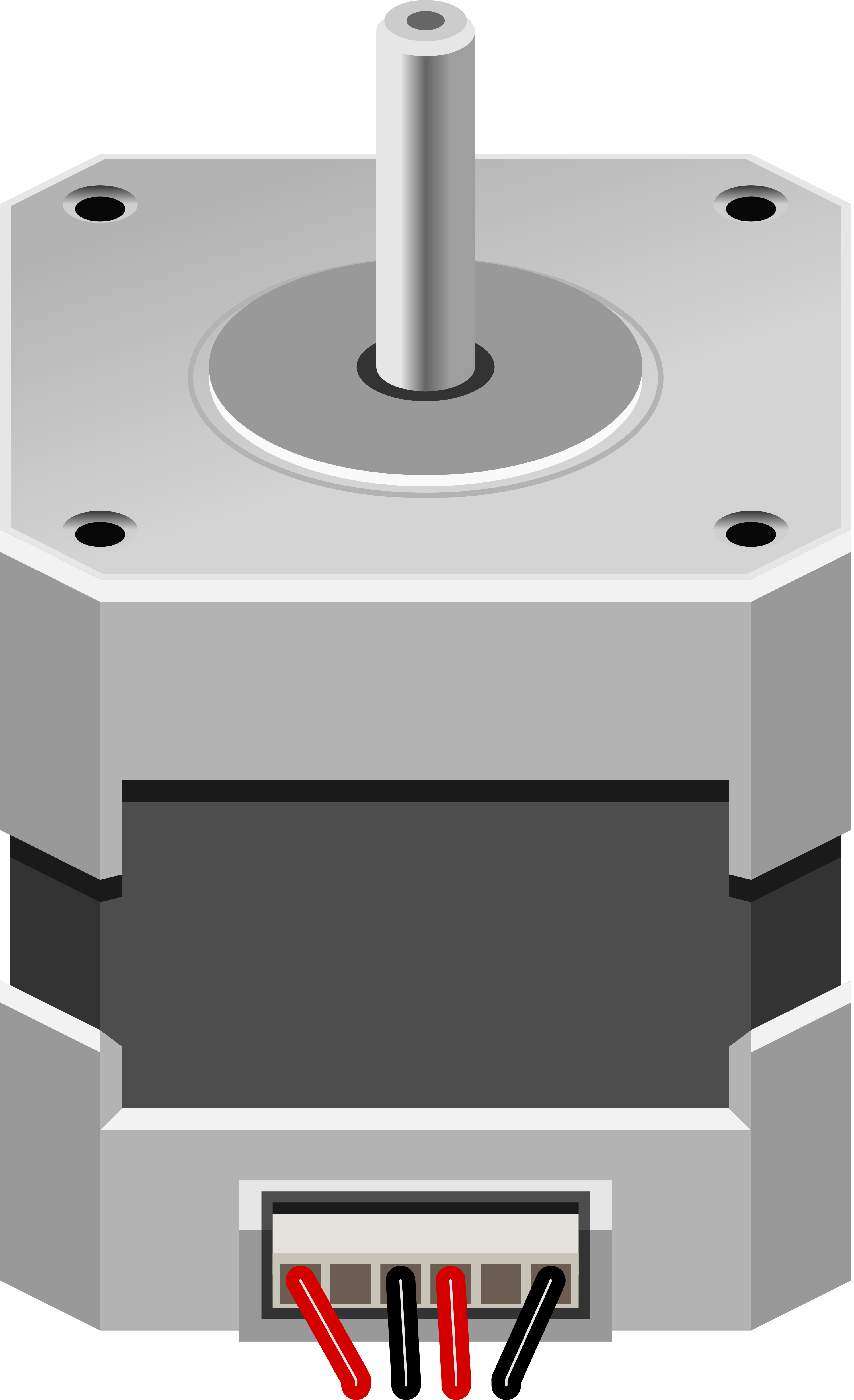
A bipolar stepper motor is an electromechanical component capable of precise position control. It operates on the principle of magnetism and energizes coil pairs in a sequence to rotate the motor shaft in discrete steps. With a full rotation divided into a number of equal steps, stepper motors are commonly used in applications requiring accurate positioning such as 3D printers, CNC machines, and robotics.

Explore Projects Built with Stepper Motor (Bipolar)

Use Cirkit Designer to design, explore, and prototype these projects online. Some projects support real-time simulation. Click "Open Project" to start designing instantly!
Stepper Motor Control Circuit with Integrated Drive and Programmable Power Supply
Image of Stepper Motor & Integrated Drive: A project utilizing Stepper Motor (Bipolar) in a practical application
This circuit connects an integrated stepper motor drive to a bipolar stepper motor, enabling controlled movement of the motor's shaft in precise increments. The stepper motor drive receives power from a programmable DC power supply, with connections for both ground and voltage supply. There is no embedded code provided, suggesting that the stepper motor drive may be pre-programmed or manually controlled.
Cirkit Designer LogoOpen Project in Cirkit Designer
Arduino-Controlled Bipolar Stepper Motor with MP6500 Driver
Image of Stepper Motor Design: A project utilizing Stepper Motor (Bipolar) in a practical application
This circuit controls a bipolar stepper motor using an Arduino UNO and an MP6500 stepper motor driver. The Arduino generates step and direction signals to the driver, which in turn powers the motor coils to create precise rotational movements. The motor's rotation direction and step count are programmable, allowing for controlled positioning in applications such as robotics or CNC machines.
Cirkit Designer LogoOpen Project in Cirkit Designer
Arduino-Controlled Stepper Motor with Potentiometer Feedback
Image of Bipolar Stepper Circuit - Stepper Follows Potentiometer: A project utilizing Stepper Motor (Bipolar) in a practical application
This circuit controls a bipolar stepper motor using an Arduino UNO and an SN754410 quadruple half-H driver. The Arduino adjusts the motor's position based on the input from a rotary potentiometer, allowing for precise control of the stepper motor's steps. The motor's power is supplied through a 2.1mm barrel jack connected to the driver's motor supply pin.
Cirkit Designer LogoOpen Project in Cirkit Designer
A4988 Stepper Motor Driver Controlled Bipolar Stepper Motor
Image of idk: A project utilizing Stepper Motor (Bipolar) in a practical application
This circuit is designed to control a bipolar stepper motor using an A4988 stepper motor driver. The driver interfaces with the motor by connecting its output pins to the motor's coils, allowing precise control of the motor's movement.
Cirkit Designer LogoOpen Project in Cirkit Designer

Explore Projects Built with Stepper Motor (Bipolar)

Use Cirkit Designer to design, explore, and prototype these projects online. Some projects support real-time simulation. Click "Open Project" to start designing instantly!
Image of Stepper Motor & Integrated Drive: A project utilizing Stepper Motor (Bipolar) in a practical application
Stepper Motor Control Circuit with Integrated Drive and Programmable Power Supply
This circuit connects an integrated stepper motor drive to a bipolar stepper motor, enabling controlled movement of the motor's shaft in precise increments. The stepper motor drive receives power from a programmable DC power supply, with connections for both ground and voltage supply. There is no embedded code provided, suggesting that the stepper motor drive may be pre-programmed or manually controlled.
Cirkit Designer LogoOpen Project in Cirkit Designer
Image of Stepper Motor Design: A project utilizing Stepper Motor (Bipolar) in a practical application
Arduino-Controlled Bipolar Stepper Motor with MP6500 Driver
This circuit controls a bipolar stepper motor using an Arduino UNO and an MP6500 stepper motor driver. The Arduino generates step and direction signals to the driver, which in turn powers the motor coils to create precise rotational movements. The motor's rotation direction and step count are programmable, allowing for controlled positioning in applications such as robotics or CNC machines.
Cirkit Designer LogoOpen Project in Cirkit Designer
Image of Bipolar Stepper Circuit - Stepper Follows Potentiometer: A project utilizing Stepper Motor (Bipolar) in a practical application
Arduino-Controlled Stepper Motor with Potentiometer Feedback
This circuit controls a bipolar stepper motor using an Arduino UNO and an SN754410 quadruple half-H driver. The Arduino adjusts the motor's position based on the input from a rotary potentiometer, allowing for precise control of the stepper motor's steps. The motor's power is supplied through a 2.1mm barrel jack connected to the driver's motor supply pin.
Cirkit Designer LogoOpen Project in Cirkit Designer
Image of idk: A project utilizing Stepper Motor (Bipolar) in a practical application
A4988 Stepper Motor Driver Controlled Bipolar Stepper Motor
This circuit is designed to control a bipolar stepper motor using an A4988 stepper motor driver. The driver interfaces with the motor by connecting its output pins to the motor's coils, allowing precise control of the motor's movement.
Cirkit Designer LogoOpen Project in Cirkit Designer

Technical Specifications

General Characteristics

  • Step Angle: Typically 1.8 degrees per step (200 steps per revolution)
  • Rated Voltage: Varies, often between 2V to 4V
  • Rated Current: Varies, often between 500mA to 2A per phase
  • Resistance per Phase: Depends on the model, often a few ohms
  • Inductance per Phase: Depends on the model, often a few mH

Pin Configuration and Descriptions

Pin Number Description Notes
1 Coil A1 Connect to a motor driver output
2 Coil A2 Connect to a motor driver output
3 Coil B1 Connect to a motor driver output
4 Coil B2 Connect to a motor driver output

Usage Instructions

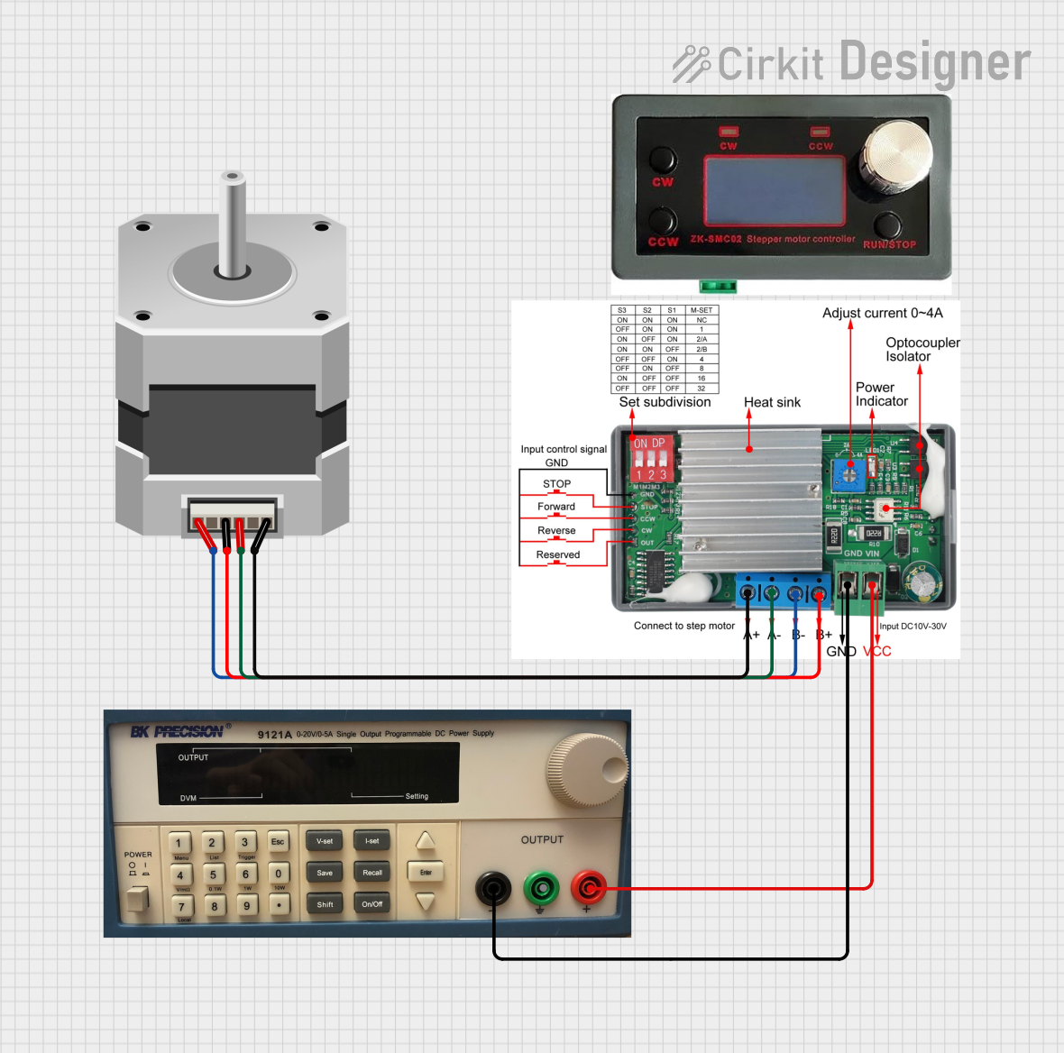
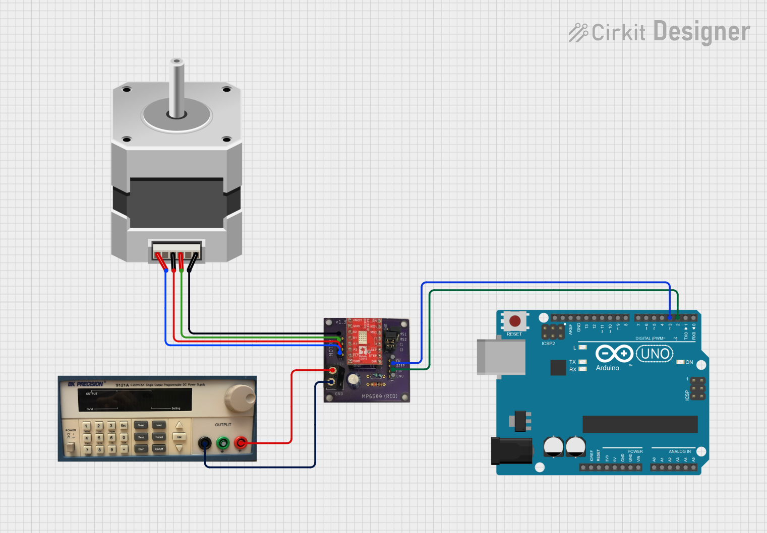
Connecting to a Circuit

  1. Motor Driver: Use a dedicated stepper motor driver capable of handling the motor's voltage and current requirements.
  2. Power Supply: Ensure the power supply matches the voltage and current specifications of the stepper motor.
  3. Microcontroller: Connect the motor driver inputs to a microcontroller like an Arduino UNO for control signals.

Best Practices

  • Current Limiting: Adjust the current limit on the motor driver to match the rated current of the motor to prevent overheating.
  • Microstepping: Use microstepping if your driver supports it to achieve smoother motion and higher resolution.
  • Decoupling Capacitors: Place capacitors close to the motor driver's power supply pins to filter noise and voltage spikes.

Example Code for Arduino UNO

#include <Stepper.h>

// Change these values based on your motor's specifications
const int stepsPerRevolution = 200;  // typically 200 steps for a 1.8 degree stepper
const int motorPin1 = 8;             // Coil A1
const int motorPin2 = 9;             // Coil A2
const int motorPin3 = 10;            // Coil B1
const int motorPin4 = 11;            // Coil B2

// Initialize the stepper library
Stepper myStepper(stepsPerRevolution, motorPin1, motorPin3, motorPin2, motorPin4);

void setup() {
  myStepper.setSpeed(60); // Set the speed to 60 RPM
}

void loop() {
  myStepper.step(stepsPerRevolution); // Move one revolution in one direction
  delay(500);
  myStepper.step(-stepsPerRevolution); // Move one revolution in the other direction
  delay(500);
}

Troubleshooting and FAQs

Common Issues

  • Motor Does Not Rotate: Check wiring connections, ensure the power supply is adequate, and verify that the motor driver is functioning.
  • Motor Vibrates but Does Not Rotate: This may indicate a misalignment of steps. Check the sequence of control signals from the microcontroller.
  • Motor Overheats: Ensure the current limit on the motor driver matches the motor's specifications. Overheating can also occur if the motor is stalled or overloaded.

FAQs

Q: Can I run a bipolar stepper motor without a driver? A: No, a bipolar stepper motor requires a driver to control the current in each coil.

Q: How do I reverse the direction of the motor? A: To reverse the direction, reverse the sequence of control signals or use the stepper library's step function with a negative number of steps.

Q: What is the difference between a bipolar and a unipolar stepper motor? A: A bipolar stepper motor has two coils and requires a change in the direction of current flow to change the magnetic field, while a unipolar stepper motor has an additional center tap on each coil and does not require current reversal.

Remember to always refer to the specific datasheet of your stepper motor model for precise specifications and wiring instructions.