Cirkit Designer Logo
Cirkit Designer
Your all-in-one circuit design IDE
Home / 
Component Documentation

How to Use Bouton-Poussoir: Examples, Pinouts, and Specs

Image of Bouton-Poussoir
Cirkit Designer LogoDesign with Bouton-Poussoir in Cirkit Designer

Introduction

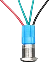
The Bouton-Poussoir, commonly known as a push-button switch, is an essential component in many electronic circuits. It is used to temporarily close or open an electrical circuit when pressed. This simple yet versatile component finds applications in various domains, including consumer electronics, industrial controls, and DIY projects. Whether you are building a simple LED circuit or a complex control system, the Bouton-Poussoir is a fundamental element that can help you achieve your design goals.

Explore Projects Built with Bouton-Poussoir

Use Cirkit Designer to design, explore, and prototype these projects online. Some projects support real-time simulation. Click "Open Project" to start designing instantly!
Pushbutton-Controlled Interface with 40-Pin Connector and UBS Power Supply
Image of connect 4: A project utilizing Bouton-Poussoir in a practical application
This circuit consists of a 40-pin connector interfacing with four pushbuttons and a UBS power supply. The pushbuttons are used as inputs to the connector, which then relays the signals to other components or systems. The UBS power supply provides the necessary 24V power to the pushbuttons and the common ground for the circuit.
Cirkit Designer LogoOpen Project in Cirkit Designer
24V Pushbutton Control Interface with 40-Pin Connector
Image of 4 på rad: A project utilizing Bouton-Poussoir in a practical application
This circuit consists of a 24V power supply unit (PSU) connected to four pushbuttons. Each pushbutton is wired such that pressing it will send a 24V signal to a corresponding general-purpose input (GP In) on a 40-pin connector. The common return path for the pushbuttons is connected to the 0V of the PSU, which is also connected to the common (Com) for input pins on the 40-pin connector, completing the circuit for each button press.
Cirkit Designer LogoOpen Project in Cirkit Designer
Toggle Switch Controlled Lamp Circuit with Banana Sockets
Image of STAIRCASE: A project utilizing Bouton-Poussoir in a practical application
This circuit consists of two toggle switches and a red lamp connected to panel mount banana sockets. The switches control the connection between the red and black banana sockets, allowing the lamp to be turned on or off depending on the switch positions.
Cirkit Designer LogoOpen Project in Cirkit Designer
Pushbutton Interface with General Purpose I/O Plug
Image of Assista GP IO: A project utilizing Bouton-Poussoir in a practical application
This circuit consists of a General Purpose Input/Output (GPIO) plug connected to four pushbuttons. Each pushbutton is wired to a unique input pin on the GPIO plug, allowing the state of each button (pressed or not pressed) to be detected individually. The common terminals of the pushbuttons are interconnected and likely serve as a ground or reference voltage connection.
Cirkit Designer LogoOpen Project in Cirkit Designer

Explore Projects Built with Bouton-Poussoir

Use Cirkit Designer to design, explore, and prototype these projects online. Some projects support real-time simulation. Click "Open Project" to start designing instantly!
Image of connect 4: A project utilizing Bouton-Poussoir in a practical application
Pushbutton-Controlled Interface with 40-Pin Connector and UBS Power Supply
This circuit consists of a 40-pin connector interfacing with four pushbuttons and a UBS power supply. The pushbuttons are used as inputs to the connector, which then relays the signals to other components or systems. The UBS power supply provides the necessary 24V power to the pushbuttons and the common ground for the circuit.
Cirkit Designer LogoOpen Project in Cirkit Designer
Image of 4 på rad: A project utilizing Bouton-Poussoir in a practical application
24V Pushbutton Control Interface with 40-Pin Connector
This circuit consists of a 24V power supply unit (PSU) connected to four pushbuttons. Each pushbutton is wired such that pressing it will send a 24V signal to a corresponding general-purpose input (GP In) on a 40-pin connector. The common return path for the pushbuttons is connected to the 0V of the PSU, which is also connected to the common (Com) for input pins on the 40-pin connector, completing the circuit for each button press.
Cirkit Designer LogoOpen Project in Cirkit Designer
Image of STAIRCASE: A project utilizing Bouton-Poussoir in a practical application
Toggle Switch Controlled Lamp Circuit with Banana Sockets
This circuit consists of two toggle switches and a red lamp connected to panel mount banana sockets. The switches control the connection between the red and black banana sockets, allowing the lamp to be turned on or off depending on the switch positions.
Cirkit Designer LogoOpen Project in Cirkit Designer
Image of Assista GP IO: A project utilizing Bouton-Poussoir in a practical application
Pushbutton Interface with General Purpose I/O Plug
This circuit consists of a General Purpose Input/Output (GPIO) plug connected to four pushbuttons. Each pushbutton is wired to a unique input pin on the GPIO plug, allowing the state of each button (pressed or not pressed) to be detected individually. The common terminals of the pushbuttons are interconnected and likely serve as a ground or reference voltage connection.
Cirkit Designer LogoOpen Project in Cirkit Designer

Technical Specifications

Key Technical Details

Parameter Value
Type Momentary Push-Button Switch
Contact Rating 50mA @ 12V DC
Contact Resistance ≤ 100mΩ
Insulation Resistance ≥ 100MΩ @ 500V DC
Dielectric Strength 1000V AC for 1 minute
Operating Temperature -20°C to +70°C
Mechanical Life 100,000 cycles

Pin Configuration and Descriptions

Pin Number Description
1 Normally Open (NO) Contact
2 Common (COM) Contact
3 Normally Closed (NC) Contact

Usage Instructions

How to Use the Component in a Circuit

  1. Identify the Pins: Determine the NO, COM, and NC pins on the Bouton-Poussoir.
  2. Connect the COM Pin: Connect the COM pin to the ground (GND) of your circuit.
  3. Connect the NO Pin: Connect the NO pin to the input of the component you wish to control (e.g., an LED or microcontroller input pin).
  4. Optional NC Pin: If you need a normally closed configuration, connect the NC pin instead of the NO pin.

Example Circuit with Arduino UNO

Here is an example of how to connect the Bouton-Poussoir to an Arduino UNO to control an LED:

Circuit Diagram

Arduino UNO          Bouton-Poussoir
   5V  ------------------->  COM
  Pin 2  ------------------->  NO
   GND  ------------------->  GND

Code Example

// Define the pin for the push-button
const int buttonPin = 2; 
// Define the pin for the LED
const int ledPin = 13; 

// Variable to store the button state
int buttonState = 0;

void setup() {
  // Initialize the button pin as an input
  pinMode(buttonPin, INPUT);
  // Initialize the LED pin as an output
  pinMode(ledPin, OUTPUT);
}

void loop() {
  // Read the state of the push-button
  buttonState = digitalRead(buttonPin);

  // Check if the push-button is pressed
  if (buttonState == HIGH) {
    // Turn the LED on
    digitalWrite(ledPin, HIGH);
  } else {
    // Turn the LED off
    digitalWrite(ledPin, LOW);
  }
}

Important Considerations and Best Practices

  • Debouncing: Mechanical push-buttons can produce noise or "bounce" when pressed. Consider using a debounce circuit or software debounce logic to ensure reliable operation.
  • Current Limiting: Ensure that the current through the push-button does not exceed its rated capacity (50mA @ 12V DC).
  • Environmental Conditions: Operate the push-button within its specified temperature range (-20°C to +70°C) to ensure longevity and reliability.

Troubleshooting and FAQs

Common Issues Users Might Face

  1. Button Not Responding: Ensure that the connections are secure and that the button is not damaged.
  2. LED Not Turning On: Verify that the LED and resistor are correctly connected and that the Arduino code is properly uploaded.
  3. Button Bouncing: Implement a debounce mechanism in your code or circuit to filter out noise.

Solutions and Tips for Troubleshooting

  • Check Connections: Double-check all wiring and connections to ensure they are correct and secure.
  • Use a Multimeter: Measure the voltage and continuity to diagnose issues with the push-button and circuit.
  • Debounce Logic: Implement debounce logic in your code to handle button bounce effectively.

By following this documentation, you should be able to effectively integrate the Bouton-Poussoir into your electronic projects, ensuring reliable and efficient operation.