How to Use RFID: Examples, Pinouts, and Specs
Introduction
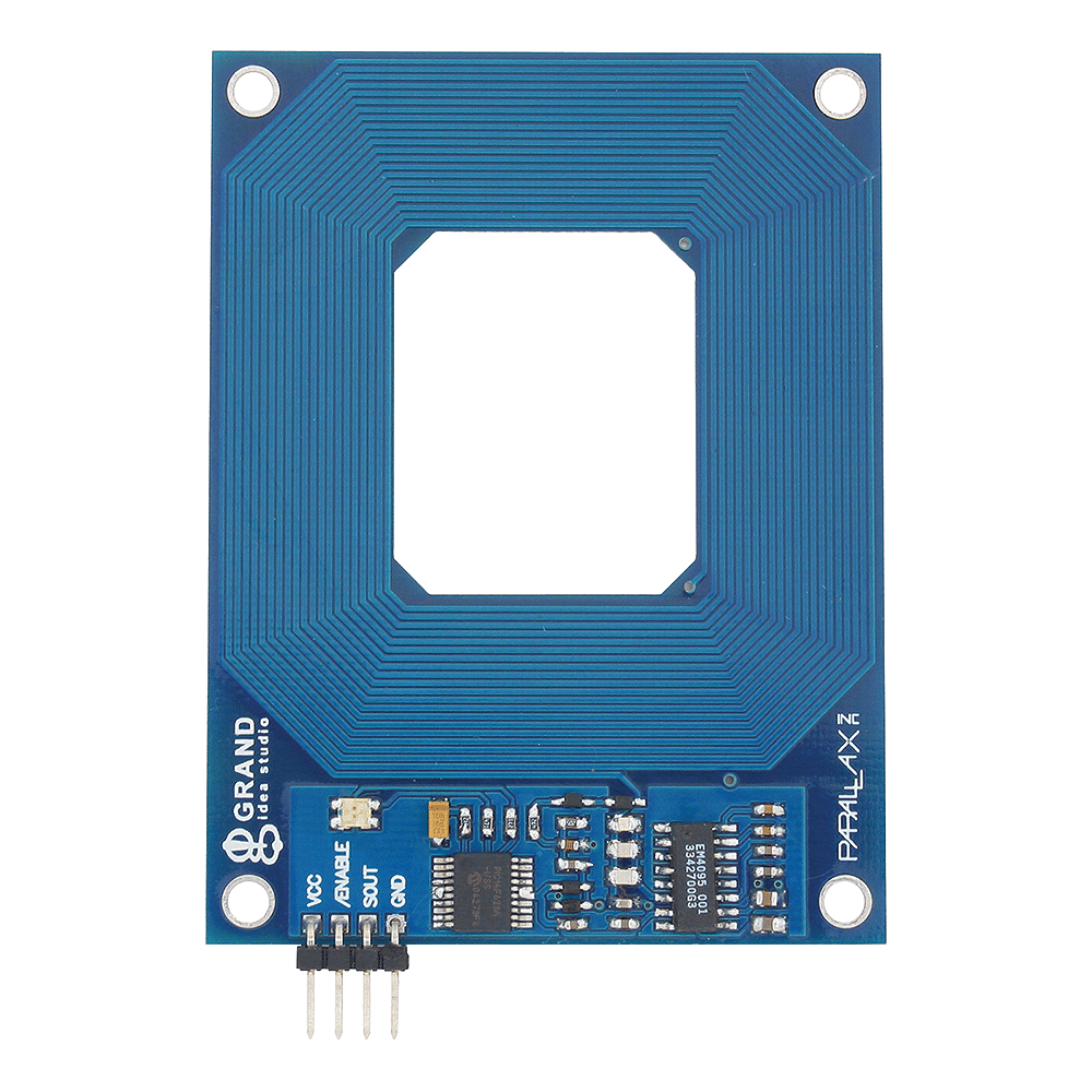
Radio Frequency Identification (RFID) is a technology that uses electromagnetic fields to automatically identify and track tags attached to objects. An RFID system consists of two main components: a reader and tags. The tags can be either passive (powered by the reader's electromagnetic field) or active (powered by an internal battery). RFID enables wireless data transmission and identification, making it a versatile solution for various applications.
Explore Projects Built with RFID

Explore Projects Built with RFID
Common Applications and Use Cases
- Inventory management and asset tracking
- Access control systems (e.g., keycards)
- Contactless payment systems
- Supply chain and logistics
- Library book tracking
- Livestock identification and monitoring
Technical Specifications
Key Technical Details
| Parameter | Description |
|---|---|
| Frequency Range | 125 kHz (Low Frequency), 13.56 MHz (High Frequency), or UHF (860-960 MHz) |
| Communication Range | Up to 10 cm (passive tags), several meters (active tags) |
| Power Supply (Reader) | 3.3V or 5V (depending on the module) |
| Data Transfer Rate | Varies by frequency and protocol (e.g., ISO 14443) |
| Protocols Supported | ISO 14443, ISO 15693, EPC Gen2, etc. |
Pin Configuration and Descriptions
Below is the pin configuration for a common RFID reader module, such as the RC522:
| Pin Name | Pin Number | Description |
|---|---|---|
| VCC | 1 | Power supply input (3.3V or 5V, depending on module) |
| GND | 2 | Ground connection |
| RST | 3 | Reset pin (active low) |
| IRQ | 4 | Interrupt pin (optional, used for advanced features) |
| MISO | 5 | Master In Slave Out (SPI data output) |
| MOSI | 6 | Master Out Slave In (SPI data input) |
| SCK | 7 | Serial Clock (SPI clock signal) |
| SDA/SS | 8 | Slave Select (SPI chip select) |
Usage Instructions
How to Use the Component in a Circuit
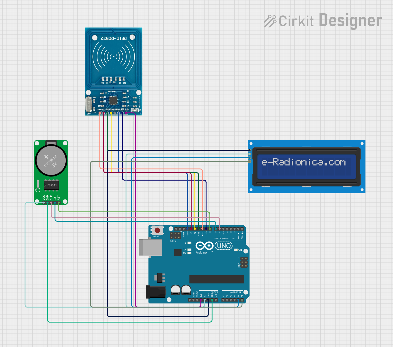
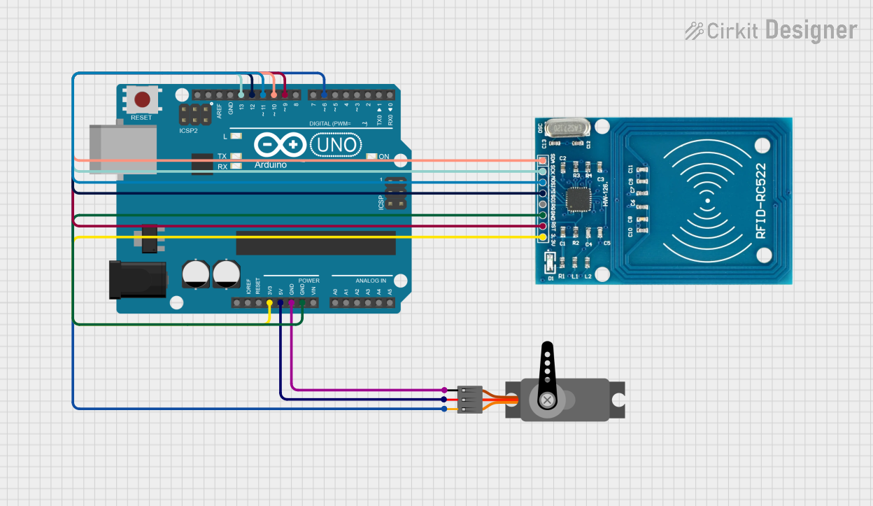
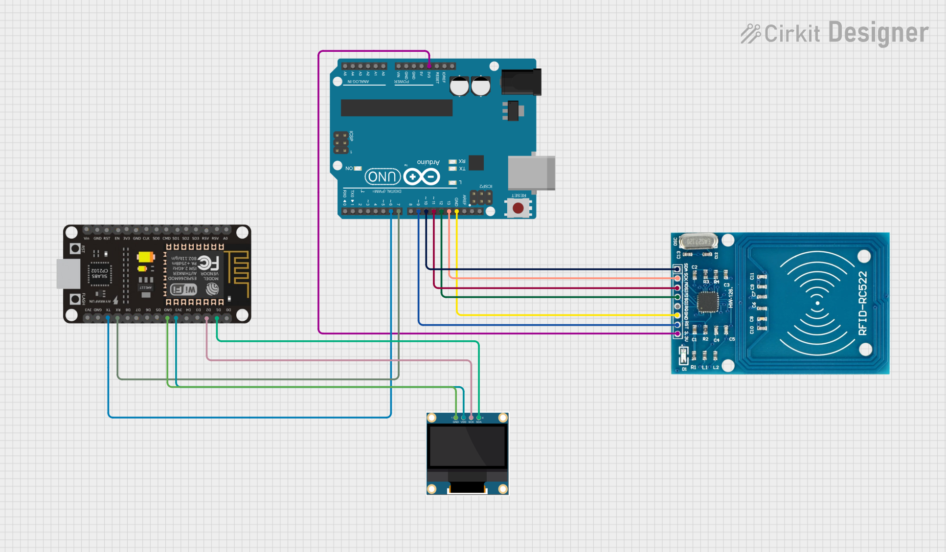
Connect the RFID Reader Module:
- Connect the
VCCpin to a 3.3V or 5V power source (check your module's specifications). - Connect the
GNDpin to the ground of your circuit. - Use the SPI interface pins (
MISO,MOSI,SCK,SDA/SS) to connect the module to a microcontroller, such as an Arduino UNO.
- Connect the
Install Required Libraries:
- For Arduino, install the "MFRC522" library from the Arduino IDE Library Manager.
Write and Upload Code:
- Use the example code below to read RFID tags.
Example Code for Arduino UNO
#include <SPI.h>
#include <MFRC522.h>

// Define RFID module pins
#define RST_PIN 9  // Reset pin connected to Arduino pin 9
#define SS_PIN 10  // Slave Select pin connected to Arduino pin 10

MFRC522 rfid(SS_PIN, RST_PIN); // Create an instance of the RFID library

void setup() {
  Serial.begin(9600); // Initialize serial communication
  SPI.begin();        // Initialize SPI bus
  rfid.PCD_Init();    // Initialize the RFID reader
  Serial.println("Place your RFID tag near the reader...");
}

void loop() {
  // Check if a new RFID card is present
  if (!rfid.PICC_IsNewCardPresent()) {
    return; // Exit if no card is detected
  }

  // Check if the card can be read
  if (!rfid.PICC_ReadCardSerial()) {
    return; // Exit if the card cannot be read
  }

  // Print the UID (Unique Identifier) of the card
  Serial.print("Card UID: ");
  for (byte i = 0; i < rfid.uid.size; i++) {
    Serial.print(rfid.uid.uidByte[i], HEX); // Print each byte in hexadecimal
    Serial.print(" ");
  }
  Serial.println();

  // Halt the card to stop communication
  rfid.PICC_HaltA();
}
Important Considerations and Best Practices
- Ensure the RFID reader module is powered with the correct voltage (3.3V or 5V).
- Keep the RFID reader away from metal objects to avoid interference.
- Use proper pull-up resistors if required by your microcontroller's SPI interface.
- For passive tags, ensure the tag is within the reader's effective range (typically 2-10 cm).
Troubleshooting and FAQs
Common Issues and Solutions
RFID Reader Not Detecting Tags:
- Ensure the tag is within the reader's range.
- Check the wiring connections, especially the SPI pins.
- Verify that the RFID module is receiving the correct power supply.
Incorrect or No Data Output:
- Confirm that the correct library (e.g., MFRC522) is installed and included in your code.
- Double-check the SPI pin assignments in your code.
Interference or Poor Performance:
- Avoid placing the RFID reader near metal surfaces or other electronic devices that may cause interference.
- Use a shielded cable for SPI connections if the module is far from the microcontroller.
FAQs
Q: Can I use multiple RFID readers in the same system?
A: Yes, but you must ensure each reader has a unique Slave Select (SS) pin to avoid SPI conflicts.
Q: What is the maximum range of an RFID reader?
A: The range depends on the type of tag and reader. Passive tags typically work within 2-10 cm, while active tags can work up to several meters.
Q: Can RFID tags be reused?
A: Yes, many RFID tags are rewritable, allowing you to update the stored data as needed.
Q: Is RFID secure?
A: Basic RFID systems are not inherently secure. For sensitive applications, use encrypted tags and secure communication protocols.