Cirkit Designer Logo
Cirkit Designer
Your all-in-one circuit design IDE
Home / 
Component Documentation

How to Use sw1801p: Examples, Pinouts, and Specs
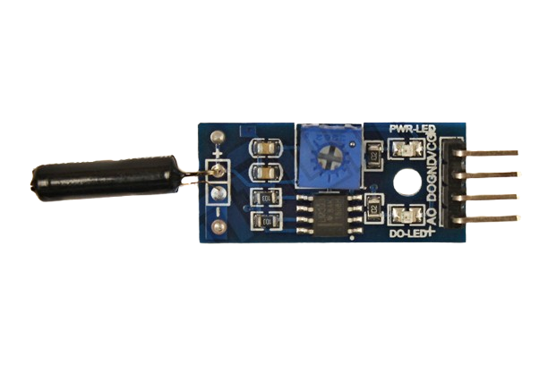
Image of sw1801p
Cirkit Designer LogoDesign with sw1801p in Cirkit Designer

Introduction

The SW1801P is a surface-mount SPDT (Single Pole Double Throw) switch designed for low-power applications. Its compact design makes it ideal for use in space-constrained environments. This versatile switch is commonly employed in signal routing, control circuits, and other applications requiring reliable switching between two outputs.

Explore Projects Built with sw1801p

Use Cirkit Designer to design, explore, and prototype these projects online. Some projects support real-time simulation. Click "Open Project" to start designing instantly!
Satellite Compass and Network-Integrated GPS Data Processing System
Image of GPS 시스템 측정 구성도_241016: A project utilizing sw1801p in a practical application
This circuit comprises a satellite compass, a mini PC, two GPS antennas, power supplies, a network switch, media converters, and an atomic rubidium clock. The satellite compass is powered by a triple output DC power supply and interfaces with an RS232 splitter for 1PPS signals. The mini PCs are connected to the USRP B200 devices via USB for data and power, and to media converters via Ethernet, which in turn connect to a network switch using fiber optic links. The antennas are connected to the USRP B200s through RF directional couplers, and the atomic clock provides a 1PPS input to the RS232 splitter.
Cirkit Designer LogoOpen Project in Cirkit Designer
Battery-Powered Raspberry Pi Pico GPS Tracker with Sensor Integration
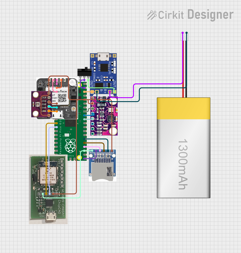
Image of Copy of CanSet v1: A project utilizing sw1801p in a practical application
This circuit is a data acquisition and communication system powered by a LiPoly battery and managed by a Raspberry Pi Pico. It includes sensors (BMP280, MPU9250) for environmental data, a GPS module for location tracking, an SD card for data storage, and a WLR089-CanSAT for wireless communication. The TP4056 module handles battery charging, and a toggle switch controls power distribution.
Cirkit Designer LogoOpen Project in Cirkit Designer
Satellite-Based Timing and Navigation System with SDR and Atomic Clock Synchronization
Image of GPS 시스템 측정 구성도_Confirm: A project utilizing sw1801p in a practical application
This circuit appears to be a complex system involving power supply management, GPS and timing synchronization, and data communication. It includes a SI-TEX G1 Satellite Compass for GPS data, an XHTF1021 Atomic Rubidium Clock for precise timing, and Ettus USRP B200 units for software-defined radio communication. Power is supplied through various SMPS units and distributed via terminal blocks and DC jacks. Data communication is facilitated by Beelink MINI S12 N95 computers, RS232 splitters, and a 1000BASE-T Media Converter for network connectivity. RF Directional Couplers are used to interface antennas with the USRP units, and the entire system is likely contained within cases for protection and organization.
Cirkit Designer LogoOpen Project in Cirkit Designer
ESP32-Based Wi-Fi Controlled Robotic System with Multiple Sensors and Motor Drivers
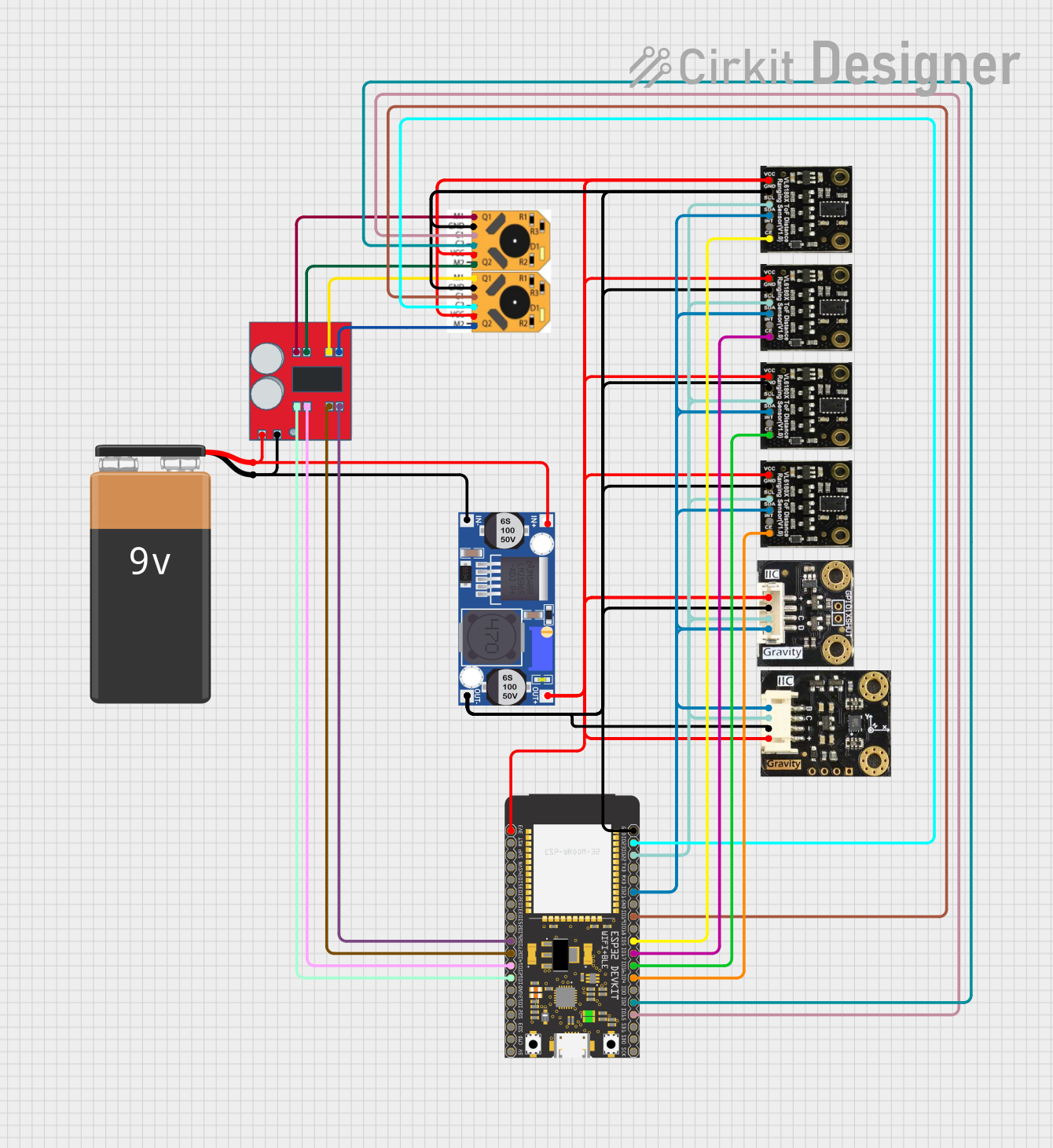
Image of mit: A project utilizing sw1801p in a practical application
This circuit is a sensor and motor control system powered by a 9V battery and regulated by a buck converter. It includes multiple sensors (SEN0245, SEN0427, I2C BMI160) connected via I2C to an ESP32 microcontroller, which also controls two N20 motors with encoders through an MX1508 DC motor driver.
Cirkit Designer LogoOpen Project in Cirkit Designer

Explore Projects Built with sw1801p

Use Cirkit Designer to design, explore, and prototype these projects online. Some projects support real-time simulation. Click "Open Project" to start designing instantly!
Image of GPS 시스템 측정 구성도_241016: A project utilizing sw1801p in a practical application
Satellite Compass and Network-Integrated GPS Data Processing System
This circuit comprises a satellite compass, a mini PC, two GPS antennas, power supplies, a network switch, media converters, and an atomic rubidium clock. The satellite compass is powered by a triple output DC power supply and interfaces with an RS232 splitter for 1PPS signals. The mini PCs are connected to the USRP B200 devices via USB for data and power, and to media converters via Ethernet, which in turn connect to a network switch using fiber optic links. The antennas are connected to the USRP B200s through RF directional couplers, and the atomic clock provides a 1PPS input to the RS232 splitter.
Cirkit Designer LogoOpen Project in Cirkit Designer
Image of Copy of CanSet v1: A project utilizing sw1801p in a practical application
Battery-Powered Raspberry Pi Pico GPS Tracker with Sensor Integration
This circuit is a data acquisition and communication system powered by a LiPoly battery and managed by a Raspberry Pi Pico. It includes sensors (BMP280, MPU9250) for environmental data, a GPS module for location tracking, an SD card for data storage, and a WLR089-CanSAT for wireless communication. The TP4056 module handles battery charging, and a toggle switch controls power distribution.
Cirkit Designer LogoOpen Project in Cirkit Designer
Image of GPS 시스템 측정 구성도_Confirm: A project utilizing sw1801p in a practical application
Satellite-Based Timing and Navigation System with SDR and Atomic Clock Synchronization
This circuit appears to be a complex system involving power supply management, GPS and timing synchronization, and data communication. It includes a SI-TEX G1 Satellite Compass for GPS data, an XHTF1021 Atomic Rubidium Clock for precise timing, and Ettus USRP B200 units for software-defined radio communication. Power is supplied through various SMPS units and distributed via terminal blocks and DC jacks. Data communication is facilitated by Beelink MINI S12 N95 computers, RS232 splitters, and a 1000BASE-T Media Converter for network connectivity. RF Directional Couplers are used to interface antennas with the USRP units, and the entire system is likely contained within cases for protection and organization.
Cirkit Designer LogoOpen Project in Cirkit Designer
Image of mit: A project utilizing sw1801p in a practical application
ESP32-Based Wi-Fi Controlled Robotic System with Multiple Sensors and Motor Drivers
This circuit is a sensor and motor control system powered by a 9V battery and regulated by a buck converter. It includes multiple sensors (SEN0245, SEN0427, I2C BMI160) connected via I2C to an ESP32 microcontroller, which also controls two N20 motors with encoders through an MX1508 DC motor driver.
Cirkit Designer LogoOpen Project in Cirkit Designer

Common Applications and Use Cases

  • Signal routing in communication devices
  • Control circuits in embedded systems
  • Audio and video signal switching
  • Low-power switching in portable electronics
  • Test and measurement equipment

Technical Specifications

The SW1801P is designed to operate efficiently in low-power environments. Below are its key technical details:

Key Specifications

Parameter Value
Switch Type SPDT (Single Pole Double Throw)
Operating Voltage 1.8V to 5.5V
Maximum Current Rating 100mA
Contact Resistance ≤ 100 mΩ
Insulation Resistance ≥ 100 MΩ
Operating Temperature -40°C to +85°C
Package Type Surface Mount (SMD)

Pin Configuration and Descriptions

The SW1801P has three pins, as described in the table below:

Pin Number Name Description
1 Common (C) The common terminal connected to the input.
2 Output 1 The first output terminal.
3 Output 2 The second output terminal.

Usage Instructions

The SW1801P is straightforward to use in a circuit. Below are the steps and considerations for integrating it into your design:

How to Use the SW1801P in a Circuit

  1. Identify the Pins: Refer to the pin configuration table to identify the Common (C), Output 1, and Output 2 pins.
  2. Connect the Common Pin: Connect the Common (C) pin to the input signal or voltage source.
  3. Connect the Output Pins: Connect Output 1 and Output 2 to the desired output circuits or devices.
  4. Control the Switching: Use an external control mechanism (e.g., a microcontroller or manual switch) to toggle between Output 1 and Output 2.

Important Considerations and Best Practices

  • Voltage and Current Ratings: Ensure the input voltage and current do not exceed the specified maximum ratings (5.5V and 100mA, respectively).
  • PCB Design: As the SW1801P is a surface-mount device, ensure your PCB design includes appropriate SMD pads for soldering.
  • Signal Integrity: For high-frequency signals, minimize trace lengths to reduce signal degradation.
  • Debouncing: If the switch is used in a mechanical system, consider implementing debouncing techniques in your circuit or software to avoid false triggering.

Example: Using SW1801P with Arduino UNO

The SW1801P can be controlled using an Arduino UNO to toggle between two outputs. Below is an example circuit and code:

Circuit Description

  • Connect the Common (C) pin to a signal source (e.g., 5V).
  • Connect Output 1 and Output 2 to two LEDs with appropriate current-limiting resistors.
  • Use a digital pin on the Arduino to control the switching mechanism.

Arduino Code

// Define the control pin for the SW1801P
const int controlPin = 7;

// Define the output pins for the LEDs
const int led1 = 8;
const int led2 = 9;

void setup() {
  // Set the control pin as output
  pinMode(controlPin, OUTPUT);

  // Set the LED pins as outputs
  pinMode(led1, OUTPUT);
  pinMode(led2, OUTPUT);

  // Initialize the switch to Output 1
  digitalWrite(controlPin, LOW);
  digitalWrite(led1, HIGH);
  digitalWrite(led2, LOW);
}

void loop() {
  // Toggle the switch every 2 seconds
  digitalWrite(controlPin, HIGH); // Switch to Output 2
  digitalWrite(led1, LOW);
  digitalWrite(led2, HIGH);
  delay(2000);

  digitalWrite(controlPin, LOW); // Switch back to Output 1
  digitalWrite(led1, HIGH);
  digitalWrite(led2, LOW);
  delay(2000);
}

Troubleshooting and FAQs

Common Issues and Solutions

  1. Switch Not Functioning Properly

    • Cause: Incorrect pin connections.
    • Solution: Double-check the pin configuration and ensure proper connections.
  2. Signal Degradation

    • Cause: Long PCB traces or high-frequency signals.
    • Solution: Minimize trace lengths and use proper grounding techniques.
  3. Overheating

    • Cause: Exceeding the maximum current or voltage ratings.
    • Solution: Ensure the input voltage is within 1.8V to 5.5V and the current does not exceed 100mA.
  4. Intermittent Switching

    • Cause: Mechanical noise or lack of debouncing.
    • Solution: Implement software or hardware debouncing techniques.

FAQs

Q: Can the SW1801P handle AC signals?
A: The SW1801P is primarily designed for low-power DC applications. For AC signals, ensure the voltage and current ratings are not exceeded.

Q: Is the SW1801P suitable for high-frequency signals?
A: Yes, but care must be taken to minimize trace lengths and maintain signal integrity.

Q: Can I use the SW1801P in a high-temperature environment?
A: The SW1801P operates reliably within a temperature range of -40°C to +85°C. Ensure the ambient temperature does not exceed this range.