How to Use Arduino-rf-nano: Examples, Pinouts, and Specs
Introduction
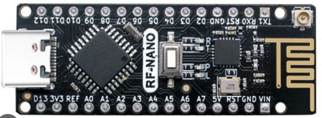
The Arduino RF Nano is a compact microcontroller board that integrates wireless communication capabilities, making it an excellent choice for IoT projects and remote control applications. It combines the functionality of an Arduino Nano with an onboard NRF24L01+ wireless transceiver module, enabling seamless wireless communication between devices. Its small form factor and versatility make it ideal for projects requiring both processing power and wireless connectivity.
Explore Projects Built with Arduino-rf-nano

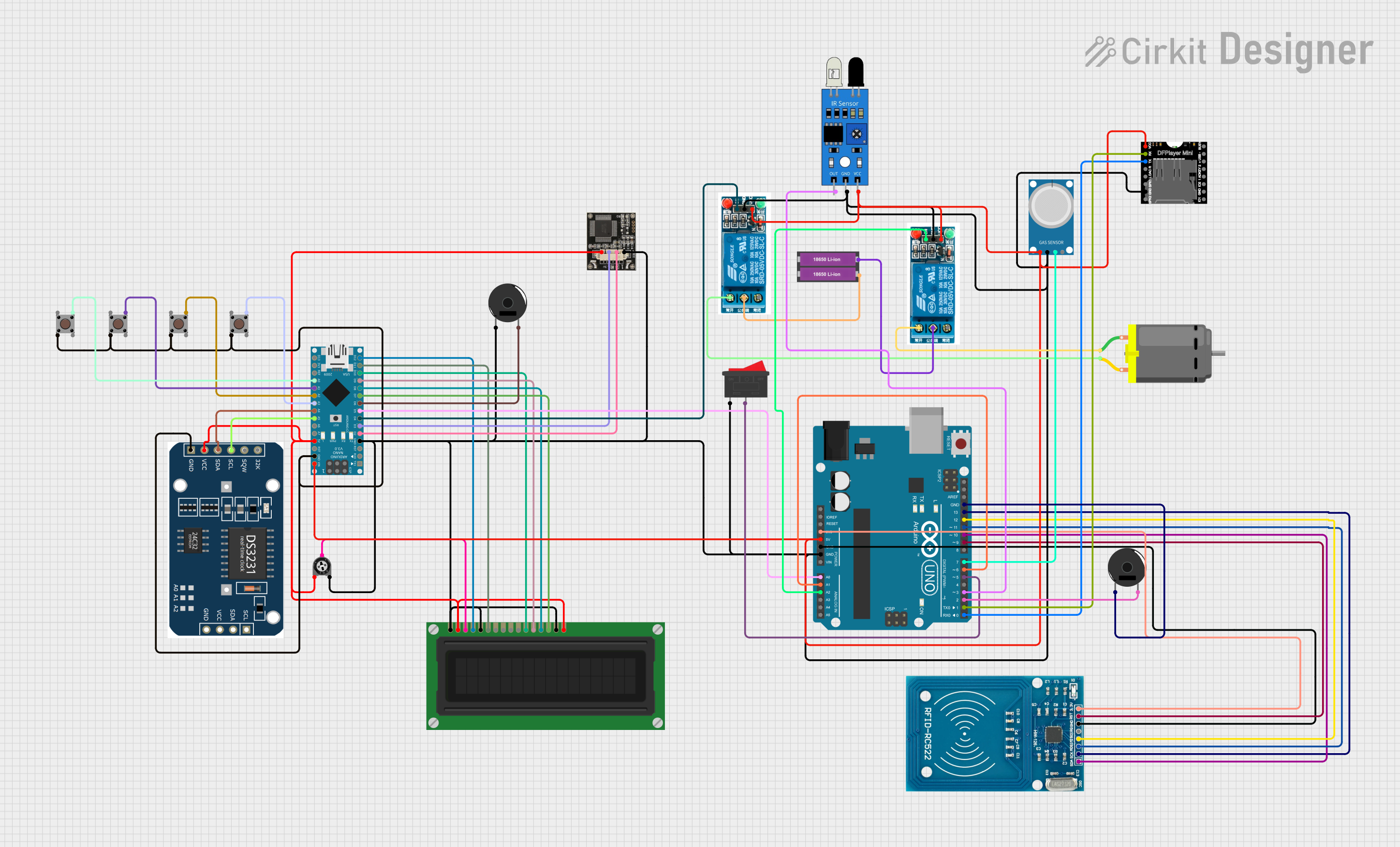
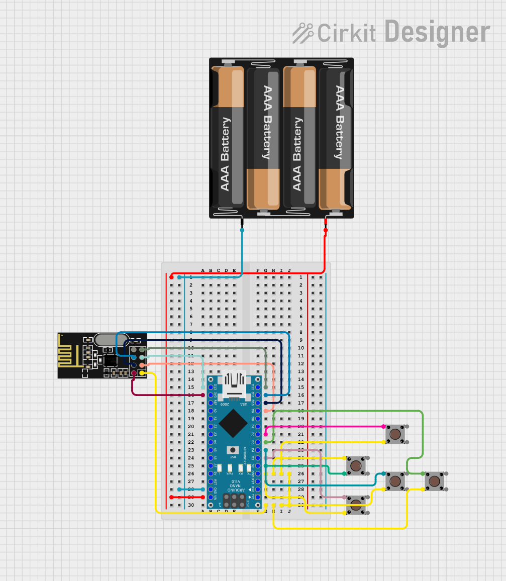
Explore Projects Built with Arduino-rf-nano
Common Applications and Use Cases
- Home automation systems
- Wireless sensor networks
- Remote-controlled devices (e.g., robots, drones)
- IoT (Internet of Things) applications
- Data logging and wireless data transmission
Technical Specifications
Key Technical Details
- Microcontroller: ATmega328P
- Operating Voltage: 5V
- Input Voltage (recommended): 7-12V
- Input Voltage (limit): 6-20V
- Digital I/O Pins: 14 (6 PWM outputs)
- Analog Input Pins: 8
- Flash Memory: 32 KB (2 KB used by bootloader)
- SRAM: 2 KB
- EEPROM: 1 KB
- Clock Speed: 16 MHz
- Wireless Module: NRF24L01+ (2.4 GHz)
- Communication Protocol: SPI for NRF24L01+ module
- Dimensions: 43 mm x 18 mm
Pin Configuration and Descriptions
The Arduino RF Nano has a similar pinout to the standard Arduino Nano, with additional connections for the onboard NRF24L01+ module. Below is the pin configuration:
General Pinout
| Pin | Type | Description |
|---|---|---|
| D0-D13 | Digital I/O | General-purpose digital input/output pins. D3, D5, D6, D9, D10, D11 support PWM. |
| A0-A7 | Analog Input | Analog input pins for reading sensor data (10-bit resolution). |
| VIN | Power Input | Input voltage to the board when using an external power source (7-12V). |
| 5V | Power Output | Regulated 5V output from the onboard voltage regulator. |
| 3.3V | Power Output | Regulated 3.3V output, useful for low-power sensors. |
| GND | Ground | Ground connection. |
| RESET | Reset | Resets the microcontroller. |
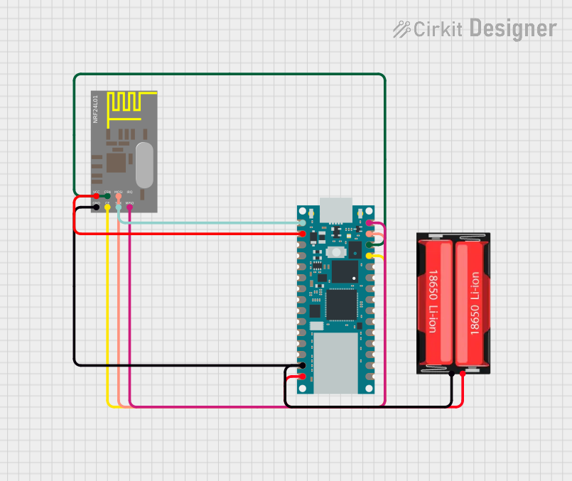
NRF24L01+ Connections
| Pin | NRF24L01+ Function | Description |
|---|---|---|
| D9 | CE | Chip Enable for the NRF24L01+ module. |
| D10 | CSN | Chip Select Not for SPI communication. |
| D11 | MOSI | Master Out Slave In for SPI communication. |
| D12 | MISO | Master In Slave Out for SPI communication. |
| D13 | SCK | Serial Clock for SPI communication. |
Usage Instructions
How to Use the Arduino RF Nano in a Circuit
Powering the Board:
- Connect the board to your computer via a USB cable for programming and power.
- Alternatively, supply 7-12V to the VIN pin or 5V to the 5V pin for standalone operation.
Programming the Board:
- Use the Arduino IDE to program the RF Nano. Select "Arduino Nano" as the board and "ATmega328P (Old Bootloader)" as the processor in the Tools menu.
- Connect the board to your computer via USB and upload your sketch.
Wireless Communication:
- The onboard NRF24L01+ module allows for wireless communication. Use the
RF24library in the Arduino IDE to configure and communicate with the module. - Connect multiple RF Nano boards or other NRF24L01+ devices to create a wireless network.
- The onboard NRF24L01+ module allows for wireless communication. Use the
Example Code for Wireless Communication
Below is an example of how to use the RF Nano to send data wirelessly to another RF Nano or NRF24L01+ device:
#include <SPI.h>
#include <nRF24L01.h>
#include <RF24.h>

// Define the CE and CSN pins for the NRF24L01+ module
#define CE_PIN 9
#define CSN_PIN 10

// Create an RF24 object
RF24 radio(CE_PIN, CSN_PIN);

// Define the address for communication
const byte address[6] = "00001";

void setup() {
  // Initialize serial communication for debugging
  Serial.begin(9600);

  // Initialize the NRF24L01+ module
  radio.begin();
  radio.openWritingPipe(address); // Set the address of the receiver
  radio.setPALevel(RF24_PA_LOW);  // Set power level to low
  radio.stopListening();          // Set the module to transmit mode
}

void loop() {
  // Data to send
  const char text[] = "Hello, RF Nano!";

  // Send the data
  bool success = radio.write(&text, sizeof(text));

  // Print the status of the transmission
  if (success) {
    Serial.println("Data sent successfully!");
  } else {
    Serial.println("Data transmission failed.");
  }

  delay(1000); // Wait 1 second before sending again
}
Important Considerations and Best Practices
- Power Supply: Ensure the board is powered with a stable voltage. Avoid exceeding the recommended voltage range to prevent damage.
- Antenna Placement: For optimal wireless performance, avoid placing the RF Nano near metal objects or other sources of interference.
- Library Compatibility: Use the latest version of the
RF24library for reliable communication. - SPI Conflicts: If using other SPI devices, ensure they do not conflict with the NRF24L01+ module's CE and CSN pins.
Troubleshooting and FAQs
Common Issues and Solutions
Problem: The board is not recognized by the Arduino IDE.
Solution:- Ensure the correct board ("Arduino Nano") and processor ("ATmega328P (Old Bootloader)") are selected in the Tools menu.
- Check the USB cable and port connection. Use a data-capable USB cable.
Problem: Wireless communication is not working.
Solution:- Verify the CE and CSN pin connections in your code match the RF Nano's pinout.
- Ensure both transmitter and receiver are using the same address and communication settings.
- Check for power supply issues or interference from nearby devices.
Problem: The board overheats during operation.
Solution:- Ensure the input voltage does not exceed the recommended range.
- Check for short circuits in your circuit connections.
FAQs
Can I use the RF Nano with other NRF24L01+ devices?
Yes, the RF Nano is fully compatible with other NRF24L01+ modules and devices.What is the maximum range of the RF Nano's wireless communication?
The range depends on environmental factors and power settings but typically ranges from 30m indoors to 100m outdoors.Can I power the RF Nano with a battery?
Yes, you can use a 7-12V battery connected to the VIN pin or a 5V battery connected to the 5V pin.
By following this documentation, you can effectively utilize the Arduino RF Nano for your wireless communication and IoT projects.