How to Use 4060: Examples, Pinouts, and Specs
Introduction
The CD4060BE is an integrated circuit (IC) that features a 14-stage binary ripple counter along with an on-chip oscillator that can be used to produce time delays or as a frequency divider in various timing applications. This versatile component is commonly used in timer circuits, frequency counters, time-delay applications, and as an oscillator in microprocessor systems.
Explore Projects Built with 4060
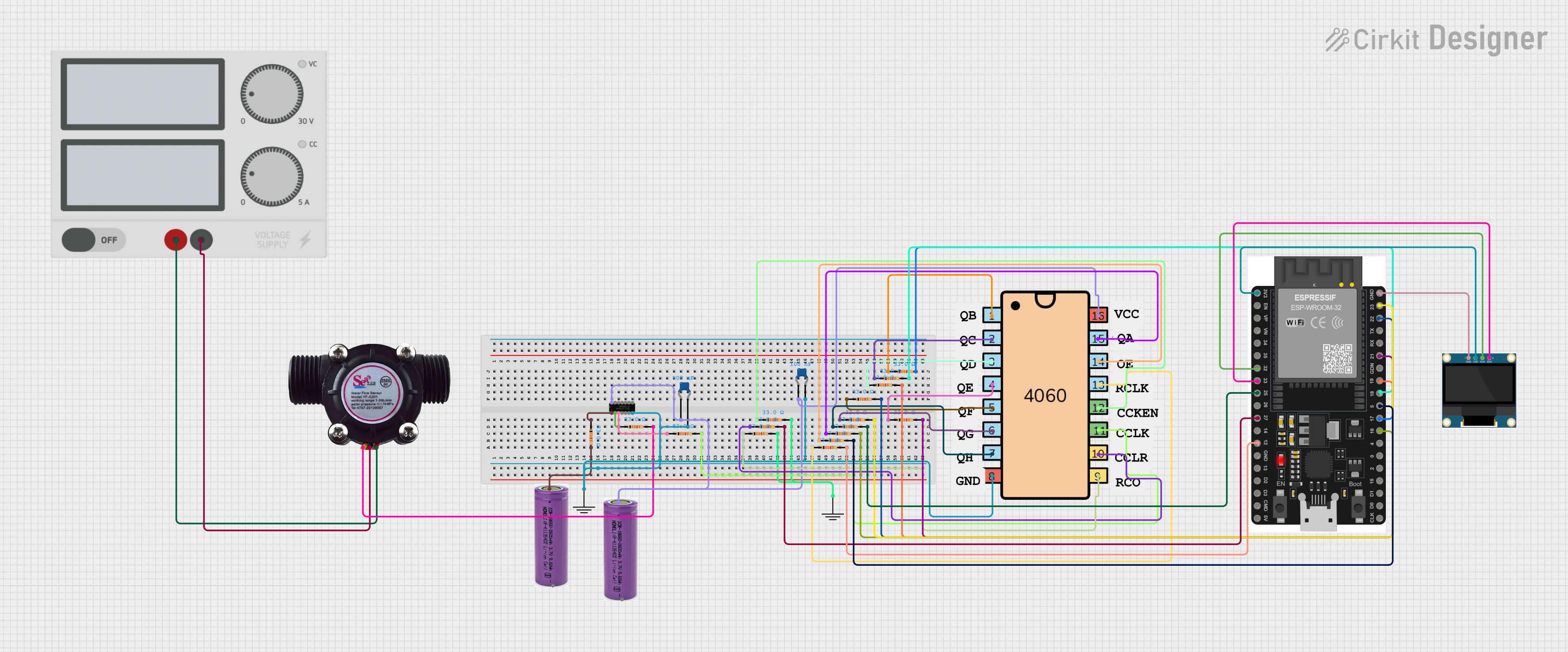


Explore Projects Built with 4060
Technical Specifications
Key Technical Details
- Supply Voltage (Vdd): 3V to 18V
- Input Voltage (Vin): -0.5V to Vdd + 0.5V
- Operating Temperature: -55°C to +125°C
- Frequency Range: Typically up to 10MHz (varies with Vdd)
- Counter Stages: 14
- Package: Available in various packages, including DIP and SOIC
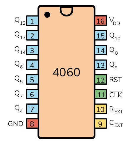
Pin Configuration and Descriptions
| Pin Number | Name | Description |
|---|---|---|
| 1 | Q4 | Output from the 4th stage of the counter |
| 2 | Q5 | Output from the 5th stage of the counter |
| 3 | Q6 | Output from the 6th stage of the counter |
| 4 | Q7 | Output from the 7th stage of the counter |
| 5 | Q8 | Output from the 8th stage of the counter |
| 6 | Q9 | Output from the 9th stage of the counter |
| 7 | Q10 | Output from the 10th stage of the counter |
| 8 | GND | Ground (0V) |
| 9 | Q11 | Output from the 11th stage of the counter |
| 10 | Q12 | Output from the 12th stage of the counter |
| 11 | Q13 | Output from the 13th stage of the counter |
| 12 | Q14 | Output from the 14th stage of the counter |
| 13 | Q0 | Output from the 1st stage of the counter |
| 14 | Q1 | Output from the 2nd stage of the counter |
| 15 | Q2 | Output from the 3rd stage of the counter |
| 16 | Vdd | Positive Supply Voltage |
Usage Instructions
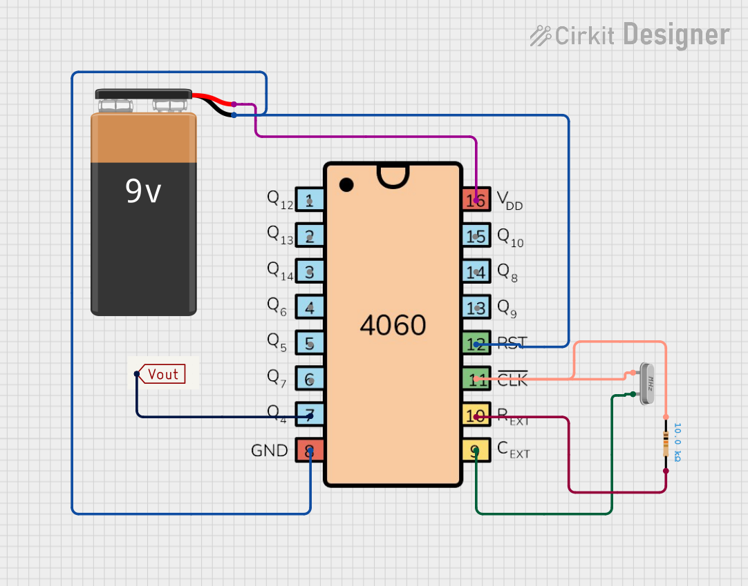
Using the 4060 as a Timer
Power Supply: Connect pin 16 (Vdd) to a positive supply voltage within the range of 3V to 18V. Connect pin 8 (GND) to the ground of your circuit.
Oscillator Configuration: To use the internal oscillator, connect a resistor between pin 16 (Vdd) and pin 10 (Rext/CLKIN) and a capacitor from pin 9 (Cext) to ground. The frequency of the oscillator can be calculated using the formula provided in the datasheet.
Counter Outputs: The Q outputs (Q0 to Q14) provide the binary count as the counter progresses. These can be used to derive timing intervals or as frequency dividers.
Resetting the Counter: To reset the counter, a low level (0V) must be applied to the reset pin (MR). This will set all Q outputs to low.
Best Practices
- Ensure that the power supply voltage does not exceed the maximum rating of 18V.
- Decouple the power supply with a 0.1µF capacitor close to the IC to filter out noise.
- Avoid applying signals to the input pins that exceed the supply voltage or go below ground level.
Troubleshooting and FAQs
Common Issues
- Counter Not Advancing: Ensure that the oscillator is correctly configured and that the power supply is within the specified range.
- Unexpected Reset: Noise on the MR (Master Reset) pin can cause the counter to reset unexpectedly. Use a pull-up resistor and proper decoupling to mitigate this.
FAQs
Q: Can the 4060 IC be used with an Arduino? A: Yes, the 4060 can be interfaced with an Arduino. The Q outputs can be connected to the digital input pins of the Arduino to read the counter state.
Q: What is the maximum frequency the 4060 can handle? A: The maximum frequency typically goes up to 10MHz, but it varies with the supply voltage and temperature.
Q: How can I calculate the output frequency? A: The output frequency is determined by the values of the external resistor and capacitor connected to the oscillator pins. Refer to the datasheet for the formula and example calculations.
Example Arduino Code
// Example code to read the state of the Q outputs from a CD4060BE IC

const int outputPins[] = {2, 3, 4, 5, 6, 7, 8, 9}; // Connect these to Q0-Q7 respectively

void setup() {
  Serial.begin(9600);
  for (int i = 0; i < 8; i++) {
    pinMode(outputPins[i], INPUT);
  }
}

void loop() {
  unsigned long counterValue = 0;
  for (int i = 0; i < 8; i++) {
    counterValue |= digitalRead(outputPins[i]) << i;
  }
  Serial.println(counterValue);
  delay(1000); // Read the counter value every second
}
This code snippet demonstrates how to read the first 8 stages of the counter outputs from the CD4060BE using an Arduino. The outputs Q0 to Q7 are connected to digital input pins 2 to 9 on the Arduino. The counter value is read every second and printed to the Serial Monitor.