
How to Use IC 7448: Examples, Pinouts, and Specs
 Design with IC 7448 in Cirkit Designer
Introduction
The IC 7448 is a BCD to 7-segment latch/decoder/driver that converts binary-coded decimal (BCD) inputs into the corresponding 7-segment display outputs. It is designed to drive common-cathode 7-segment displays, making it an essential component for numerical display applications. The IC simplifies the process of converting digital signals into human-readable numerical values on displays.
Explore Projects Built with IC 7448
 Open Project in Cirkit Designer
 Open Project in Cirkit Designer
 Open Project in Cirkit Designer
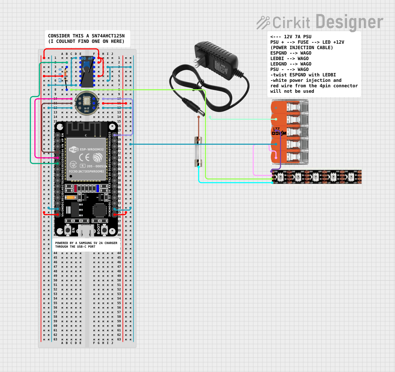 Open Project in Cirkit Designer
Explore Projects Built with IC 7448
Open Project in Cirkit DesignerOpen Project in Cirkit DesignerOpen Project in Cirkit DesignerOpen Project in Cirkit DesignerCommon Applications and Use Cases
- Digital clocks and timers
- Electronic meters and counters
- Calculators
- Embedded systems requiring numerical displays
- Educational projects involving 7-segment displays
Technical Specifications
The IC 7448 is a TTL (Transistor-Transistor Logic) device with the following key specifications:
| Parameter | Value |
|---|---|
| Supply Voltage (Vcc) | 4.75V to 5.25V |
| Input Voltage (High) | 2V (minimum) |
| Input Voltage (Low) | 0.8V (maximum) |
| Output Voltage (High) | 2.4V (minimum) |
| Output Voltage (Low) | 0.4V (maximum) |
| Maximum Output Current | 40mA |
| Power Dissipation | 500mW (maximum) |
| Operating Temperature Range | 0°C to 70°C |
Pin Configuration and Descriptions
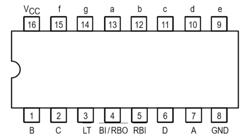
The IC 7448 comes in a 16-pin DIP (Dual Inline Package). Below is the pinout and description:
| Pin Number | Pin Name | Description |
|---|---|---|
| 1 | B | BCD Input (Bit 1) |
| 2 | C | BCD Input (Bit 2) |
| 3 | Lamp Test (LT) | Activates all segments for testing purposes (active low) |
| 4 | RBI | Ripple Blanking Input (used for blanking leading zeros) |
| 5 | D | BCD Input (Bit 3) |
| 6 | A | BCD Input (Bit 0) |
| 7 | Blank (BI) | Blanking Input (disables all segments when active low) |
| 8 | GND | Ground (0V) |
| 9 | f | Segment Output (f) |
| 10 | g | Segment Output (g) |
| 11 | e | Segment Output (e) |
| 12 | d | Segment Output (d) |
| 13 | c | Segment Output (c) |
| 14 | b | Segment Output (b) |
| 15 | a | Segment Output (a) |
| 16 | Vcc | Supply Voltage (+5V) |
Usage Instructions
How to Use the IC 7448 in a Circuit
- Power Supply: Connect pin 16 (Vcc) to a +5V power supply and pin 8 (GND) to ground.
- BCD Inputs: Connect the BCD inputs (pins 1, 2, 5, and 6) to the digital signals representing the binary-coded decimal value.
- 7-Segment Display: Connect the segment outputs (pins 9–15) to the corresponding segments of a common-cathode 7-segment display.
- Control Pins:
- Use the Lamp Test (LT) pin to test all segments by pulling it low.
- Use the Ripple Blanking Input (RBI) and Blanking Input (BI) pins for blanking control as needed.
- Resistors: Place current-limiting resistors (typically 330Ω to 1kΩ) between the segment outputs and the 7-segment display to prevent excessive current.
Important Considerations and Best Practices
- Ensure the IC operates within the specified voltage range to avoid damage.
- Use appropriate pull-up or pull-down resistors on control pins if they are not actively driven.
- Avoid exceeding the maximum output current to prevent overheating or damage to the IC.
- For proper blanking of leading zeros, connect the RBI pin to the output of the previous stage in multi-digit displays.
Example: Connecting IC 7448 to an Arduino UNO
Below is an example of how to interface the IC 7448 with an Arduino UNO to display numbers on a 7-segment display.
// Arduino code to display numbers 0-9 on a 7-segment display using IC 7448

// Define BCD input pins connected to Arduino
const int A = 2; // BCD Input A (Pin 6 on IC 7448)
const int B = 3; // BCD Input B (Pin 1 on IC 7448)
const int C = 4; // BCD Input C (Pin 2 on IC 7448)
const int D = 5; // BCD Input D (Pin 5 on IC 7448)

void setup() {
  // Set BCD input pins as outputs
  pinMode(A, OUTPUT);
  pinMode(B, OUTPUT);
  pinMode(C, OUTPUT);
  pinMode(D, OUTPUT);
}

void loop() {
  for (int i = 0; i < 10; i++) { // Loop through numbers 0-9
    displayNumber(i);            // Display the current number
    delay(1000);                 // Wait for 1 second
  }
}

void displayNumber(int num) {
  // Convert the number to BCD and write to the IC 7448 inputs
  digitalWrite(A, num & 0x01);   // Write bit 0 to pin A
  digitalWrite(B, (num >> 1) & 0x01); // Write bit 1 to pin B
  digitalWrite(C, (num >> 2) & 0x01); // Write bit 2 to pin C
  digitalWrite(D, (num >> 3) & 0x01); // Write bit 3 to pin D
}
Troubleshooting and FAQs
Common Issues and Solutions
No Output on the 7-Segment Display:
- Ensure the IC is powered correctly (check Vcc and GND connections).
- Verify that the BCD inputs are receiving the correct signals.
- Check the connections between the IC outputs and the 7-segment display.
Incorrect Digits Displayed:
- Confirm that the BCD inputs are correctly wired and sending the intended binary values.
- Check for loose or incorrect connections to the 7-segment display.
Segments Not Lighting Up:
- Verify that the Lamp Test (LT) and Blanking Input (BI) pins are not active (both should be high).
- Ensure the current-limiting resistors are of appropriate value.
Overheating of the IC:
- Check if the output current exceeds the maximum rating (40mA per segment).
- Use resistors to limit the current through the 7-segment display.
FAQs
Q1: Can the IC 7448 drive a common-anode 7-segment display?
No, the IC 7448 is designed specifically for common-cathode 7-segment displays.
Q2: What happens if I input a BCD value greater than 9?
The IC 7448 does not decode values greater than 9. For inputs 10–15, the output will be undefined.
Q3: Can I use the IC 7448 with a 3.3V power supply?
No, the IC 7448 requires a supply voltage between 4.75V and 5.25V for proper operation.